DEF Sensor Simulator – Arduino DUE (Original Build)
Assembling a DEF Sensor Simulator Using an Arduino DUE with CAN Card
Following is the build process for the original version of the DSS hardware and software from September 2021. This is still a valid solution and requires no soldering, however, check the Quick Build page for the currently recommended solution which is likely to be smaller and less expensive.
Only basic electrical and DIY skills are required for the hardware assembly, no soldering is needed. The software installation in this procedure requires a Windows system and only involves typing some simple commands.
Before you begin, please click here to read an important compatibility notice regarding the ECM (Electronic Control Module, aka Engine Computer) and info on compatible DEF head connectors.
If you run into difficulty post a comment at the bottom of this page.
Parts – order these items:
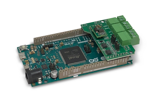
- Arduino Due with Can bus & Extended Power – from Copperhill Technologies
Note: Be sure to click YES for the Extended Input Power Range Option! As of 6/2022 cost with the Extended Input Power Range option is in excess of $150.If the above board is out of stock you can order the alternative found here.If the alternate has sold out as well, you can try and order the 2 individual pieces separately, the first is the Arduino by itself and the second is the CAN Bus daughter board from Copperhill. Both of these items are found at the following links: - DT-4 Extension Cable – from Diode Dynamics $15 + shipping
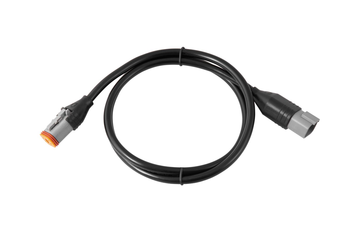
Note this connector style will not be correct for all applications:
– Freightliner owners please see this page. - Waterproof Enclosure – from Amazon $14.99

- Optional PG-9 size Waterproof Cable Gland – from Amazon $0.70 This item can also be found at most local hardware stores, auto parts stores as well as some Home Depot and Lowes.

Tools:
- Drill
- Wire cutters / Strippers
- Small screw driver
- Ohm meter
- Silicone (or Weather Gland)
- 5/16″ drill bit (if not using weather gland)
- 9/16″ drill or step bit (if using weather gland)
Download the software:
Download the following file to your windows desktop – DEF Sensor Simulator Install Files
Make sure you remember where your download went to (Downloads, or Desktop) you will need to know where it is at later.
If you get a message indicating the download will harm your computer (it won’t that is just because it is new and not officially recognized by windows), see here and/or this 16 second video for instructions.
Extract and install the software:
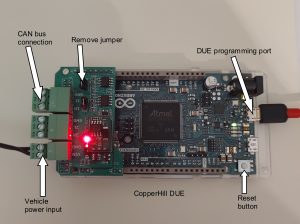
- Plug the USB Cable into the Programming Port of your Arduino Board, port closest to the power connector. The cable will provide power to the board and facilitate the data transfer.
- Plug into a USB port on your computer.
- Open the device manager on your PC, expand the Ports (Com & LPT) group, make note of what usb com port your Arduino is on. You can Unplug and re-plug the connector on the Arduino or your PC to verify which port it is using. Write this port number down. LEAVE the Arduino PLUGGED into your USB port.

- Extract and install the software that you downloaded by double clicking the package that you downloaded called DEF Emulator Install Files (x32).exe. Note: When opening the file, you might get a “Windows protected your PC” message box -> Click “Run anyway”. If prompted “Do you want this file to make changes to your hard drive?”, click “Yes”. See here for more info.
- Answer Next to all the extract to directories, do not change the install directories they are needed later.
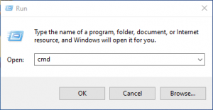
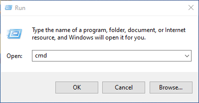
- Right mouse click on the start button on the task bar, choose Run.
- In the Run command box Type CMD and press enter or Select OK
- In the open command prompt windows dialogue box type the following: c:\AVRprog\program.bat DUE 6
Note: you will need to change the number 6 in the above example to the com port number you wrote down in step three now press Enter. - You should see something similar to the following
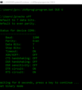 :
: - And when it is finished:
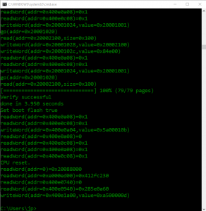
- When the install has finished, unplug the Arduino from the USB cable, the computer stuff is done.


Assemble the hardware:
- Take the 1 Meter DT Extension cable that you purchased in Hardware step 2 and cut the off the flat end with the exposed orange silicone as shown in the picture below, approximately 6 inches from the connector. The short end with the Orange silicone connector will not be used electrically, but if desired can be used as a “dust cap” for the DEF head sensor connector when the DSS is in use.Note: Freightliner applications will require a different connector/cable – for more information click here.
- Take your waterproof case and drill a hole 3/8 in size in the upper corner (large enough to pass the cable through. Alternately drill a hole large enough to accept the weather gland (9/16) and install it now (weather gland shown in photo).
- Trim the main wire covering about 2 inches back, careful not to nick any of the individual wires.
- Trim and strip ¼ of insulation off each wire and go ahead and twist the bare wire to keep it from fraying out.
- Just in case, it is suggested to identify the correct color coding using an OHM meter. Put your meter on the ohms scale and test each pin to ensure continuity to the appropriate colored wire. Looking at the business end of the plug:
- Top Left +12 (Should be Yellow)
- Bottom Left Ground (should be Blue)
- Top right – Can L (should be Red)
- Bottom Right – Can H (should be Black)
- If your colors are different that is ok just make note what function each color is for (+12, GND, CAN-H, CAN-L) – the position on the connector is what is important.
- The Arduino DUE daughter board (opposite end from the usb connection ) has green screw terminals and is marked with the following: VIN, GND, 2H, 2L, GND, 1H, 1L, GND. You will only be using VIN, GND, 1H, 1L. To prepare the green terminal blocks for inserting the wires, it is best to make sure they are fully open as shown below.
- Using the photo below, or the wires you identified in step 5 if the color coding is different wire it up as shown below. Note: It may not be obvious, but the green part with the screws unplugs from the green part on the circuit board so go ahead and remove those connectors, it will be much easier to attach the wires.
- In the step above use plenty of light and a magnifier if necessary to make certain there are no errant strands hanging out of the screw terminals that could potentially cause a short. It is OK to cut off a few strands if needed to make the wires fit easier, especially on the thicker wires.
- Disable the termination resistors by removing the jumpers shown in the photo below.
- Adjust the length of main wire in the weatherproof box to position the Arduino in the box.
- As a final test use your OHM meter to double check you have continuity from the each plug pin to the appropriate Arduino connection.
- If you did not use a weather grommet on the cable then now is a good time to place a dab of silicone on the opening of the box where the wire passes through.
- Your Def Sensor Simulator build is complete.


Connecting to your motorhome CAN network:
- Make sure that before you unplug your def head that the ignition is turned off, then unplug your def head. You may need to cut a zip tie to provide working slack in the wiring.
- Plug the simulator into the connection to your chassis wiring where the def head was plugged in.
- Turn on your ignition, some or all of the fault codes should go away and the Check Engine and MIL (Malfunction Indicator Lamp) lights should extinguish within a few minutes.
- If some codes remain, to clear your codes you will need to turn your ignition on (let all systems come up, about 20 seconds), then start your engine and fast idle for 5-6 minutes, shut down for 90 seconds, turn ignition on (wait for systems to boot 20 sec) start engine and fast idle for 5 min. You will do this a total of 3 times on the 4 cycle the codes should clear to the inactive status.
Note: on older engines or engines with older ECM software, some codes may not completely clear on their own. In this case code clearing intervention may be required. This is something that is still under study, see the Troubleshooting section for more info.

I am on the step where I extract and install the software that I downloaded.
I have a new Dell laptop with Windows 11 Home Version 21H2. I downloaded the .exe file and it made the directories at C:\AVRRrog. I am trying to program a Arduino-Based ECU Development Board with Dual CAN Bus Interface JDCOM.ECU.DUE-X. I see a file in the “DUE” folder called DEF_Sensor_Emulator.ino.bin . When I double click it, it askes me what program do you want to run it with. Not sure what to do next. I am stuck. Not a real computer expert here. Help!
info.
Answer Next to all the extract to directories, do not change the install directories they are needed later.
Right mouse click on the start button on the task bar, choose Run.
Ken check ur email for a new msg fm Vchanko.defsim@gmail.com
Why did you apparently stop at Step 5 from the instructions under the Section called “Extract and Install the Software” above (which you quoted. Step 5…”Right mouse click on the start button on the task bar. Choose Run…”?
Just continue to follow steps 6 through 11 and it should be programmed.
I just purchased this ECU board see below, which it claims extended power 7-36 VDC.
My question, do i still need to purchase the separate dual CAN interface board with extended power for $60. ? or am i set to go?
BTW thanks for all you’ve done for us RV owners,
Ed K
COPPERHILL TECHNOLOGIES
Arduino-Based ECU Development Board With Dual CAN Bus Interface
$99.95
SKU:
JCOM.ECU.DUE-X
Hi Ed. The board that you bought already comes with a “daughter board” which provides the Dual CANBUS controllers and connectors along with the “Extended Power Option”. So that is everything you will need. Good luck!
Is anyone willing to build one and sell it to me. Not technical enough to build my own? Thanks
Yes
Text me 4802974887
Hello,
I just completed a simulator using your instructions, they are so thorough even I could follow them !
My question is, should I test the dss in the motor home? I have not had a failure and don’t want to risk introducing a problem un necessarily.
Thank you
At this point the DSS design has been proven to be pretty bulletproof. The only problems have almost exclusively been due to wiring errors or problems getting it to program. So if you have doublechecked your wiring (both that you done have any shorts or open circuits and that the wires go to the right place on the connector as well as the board) then you can be pretty confident that it will work.
On the other hand, just plugging it up & turning the key on isn’t really a big deal. If you do get faults for whatever reason then just reconnecting the known good OEM sensor and doing 3X 5 minute idle cycles will clear the codes.
I have a new Dell Inspirion with windows 11.I down loaded the ptogram to the laptop in in the locatin stated, but when i try to program the simulator the laptop wants yo use windows media playerthat pulls up an error and asks if I still want to try it. I click yes and still says there is s problem with the format. I don’t know what to do.
Mark, I sent you an email with a request that we talk on the phone. It’ll be quicker and easier than messaging back and forth. Check your email
Hey Vic,
I am available if you want to call. I think I figured it out but would like to still talk.
Greetings,
Is there any information regarding the software file itself? The programming and what exactly is it saying to the ECM? Also just curious, why aren’t we able to just use a variable resistor, does the def level sensor not work like a fuel level sensor? Just asking for my own knowledge so I can help others. Thank you for your time and energy in the matter.
Hi Vincent, I can tell you in general how the DSS does what it does. First though as to your question about just using a variable resistor to set an analog voltage, no, that will not work in this case. The parameters for the DEF tank sensor (as well as many, many more sensors and systems unrelated to the DEF system) are transmitted to the ECM using datagrams that are specified in format as well as content by a Society of Automotive Engineers Standard known as J1939. The data moves (along with a very large number of simultaneous messages from all of the other vehicle systems necessary to operate the vehicle) on an asynchronous electrical network commonly called CANBUS for Controller Area Network BUS. CANBUS is similar to the older RS-485 industrial serial date network standard. In the most common DEF QLS sensors, the quality of the DEF fluid is determined by using an ultrasonic transducer to measure the speed of sound through the liquid and after correcting for temperature that speed is used to determine the specific gravity AKA the “quality” of the DEF. The tank fluid level measurement also uses a similar ultrasonic approach (essentially SONAR) to determine the distance from the sensor’s transducer to the surface of the liquid. The temp is just measured with a thermistor as you assumed, but the analog thermistor output is never used directly. It is processed into a digital value before being used. The raw data from all the sensors is processed by a microprocessor in the DEF head and formatted into J1939 CANBUS data and that data is then sent a couple of times per second onto the vehicle data network. The ECM then decodes the information for further use in its proprietary vehicle operational logic.
So that’s the general description of how things work. I’m not sure why you wanted to know but I hope it will help.
It looks like the simulator I acquired is actually a Arduino DUE original build.
I heard there was a software update. If so, where is it located?
Is there a way to test when hooked up to a computer?
No, the software on this site (in the instructions for programming the Copperhill DUE with the extended power option-each flavor of hardware uses its own version of software).