DEF Sensor Simulator – Arduino UNO
Assembling a DEF Sensor Simulator Using an Arduino UNO
Only basic electrical and DIY skills are required for the hardware assembly. The software installation in this procedure can be done from Windows.
Before you begin, please click here to read an important compatibility notice regarding the ECM (Electronic Control Module, aka Engine Computer) and info on compatible DEF head connectors.
If you run into difficulty post a comment at the bottom of this page.
Please read through all the instructions FIRST before beginning the project. There are web site links embedded in the instructions to help obtain parts.
Note: It is highly recommended that you program the Arduino board before starting the assembly of the DEF simulator. Please see the Programming section at the bottom of this post.
Parts:
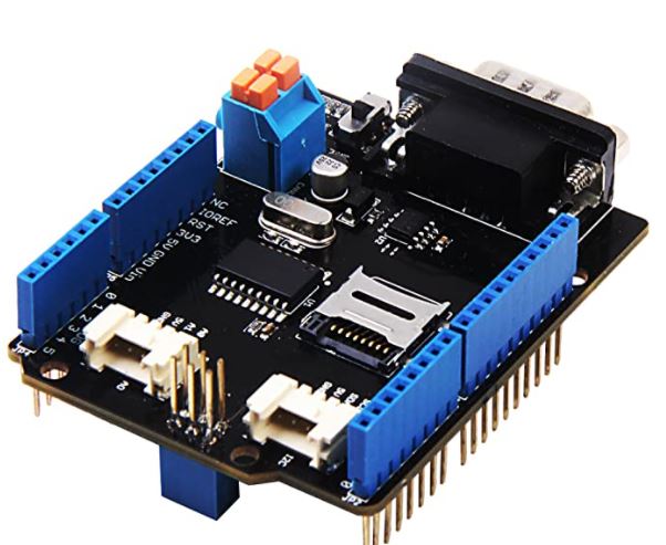
The UNO/ATMega2560 boards require the use of an additional board called a CAN shield. The Arduino UNO or equivalent can be purchased from online retailers such as Amazon.
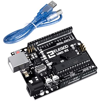
The CAN shield (V2) is made by Seeed Studios and can be purchased directly from them, Amazon or other online retailers. Here is a link for Amazon.
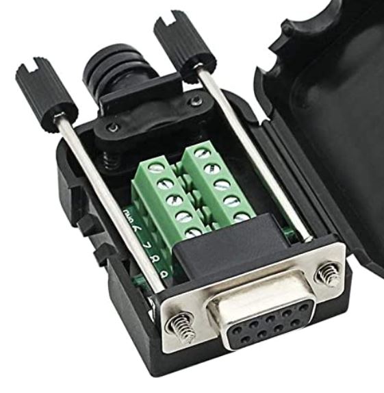
The assembly will also need a female DB9 connector to attach the wires to the vehicle connector. This connector can be purchased from Amazon:
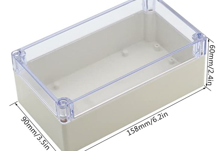
The entire assembly of the UNO with the DB9 connector is slightly larger than the size of an Arduino DUE, so it will require a larger enclosure. Here is one from Amazon that will work:
Assembly:
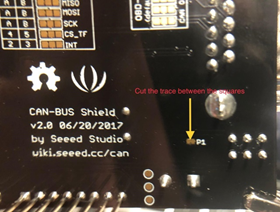
The Seed CAN shield will need a small wire trace to be cut before use. Cutting this run removes a termination resistor that is not needed when connecting the simulator to the vehicle. The wire trace is connected between the blocks labeled P1 on the back side of the shield. The run can be cut with an X-acto knife or box cutter. Do not cut too deeply so as to damage the board. The trace is not very thick.
The cable and waterproof gland nut used on the DUE assembly can also be used with the UNO.
As an alternative to the “Gland nut” you can use a rubber grommet, which can be purchased from most hardware stores, such as ACE Hardware. Just get one that will fit your cable diameter. You could also just fill the hole in the box where the cable goes through with silicone sealant.
The wiring connections on the 4 pin DT-4 connector are: +12v, ground, CAN-H and CAN-L.
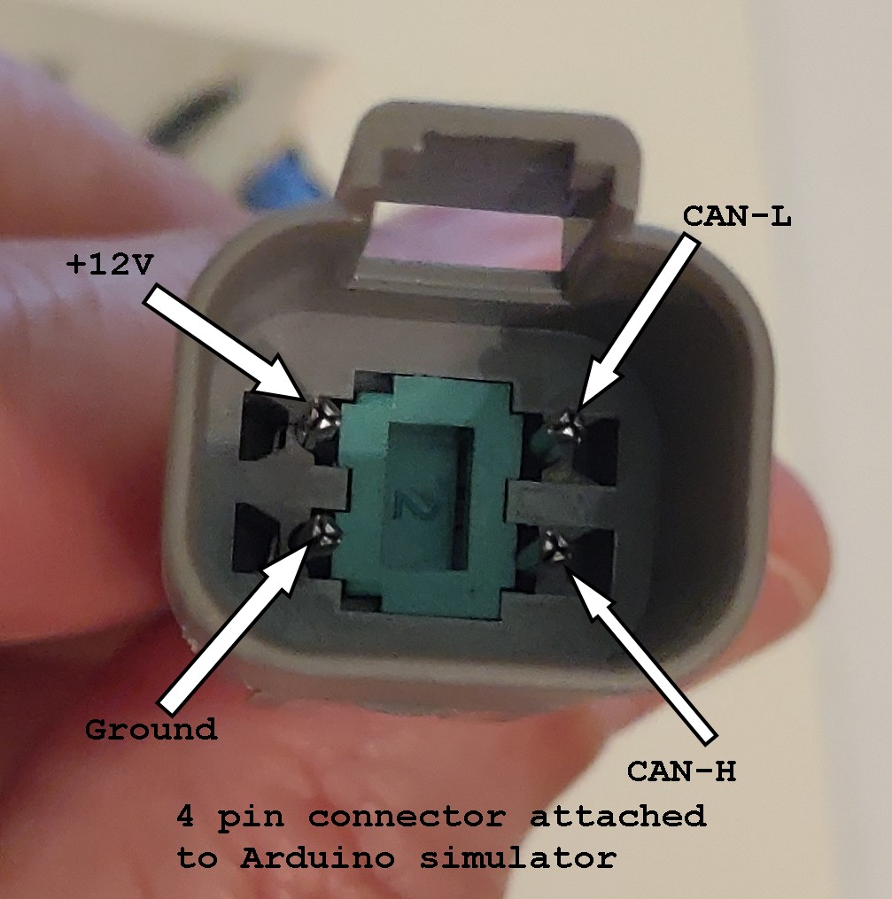
The wires associated with these pins (above picture) are connected to the DB9 connector via the screw terminals.
Strip about 3/16 inch of insulation off each wire end and connect to the DB9 screw terminals. If the wire is too thick, cut off a few strands. Be sure there are no stray wire strands touching anything.
DB9 connections:
Pin 2 = ground Pin 3 = CAN-H Pin 5 = CAN-L Pin 9 = +12v
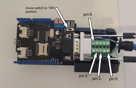
Make sure to move the switch on the CAN shield to the “ON” position (see Picture above).
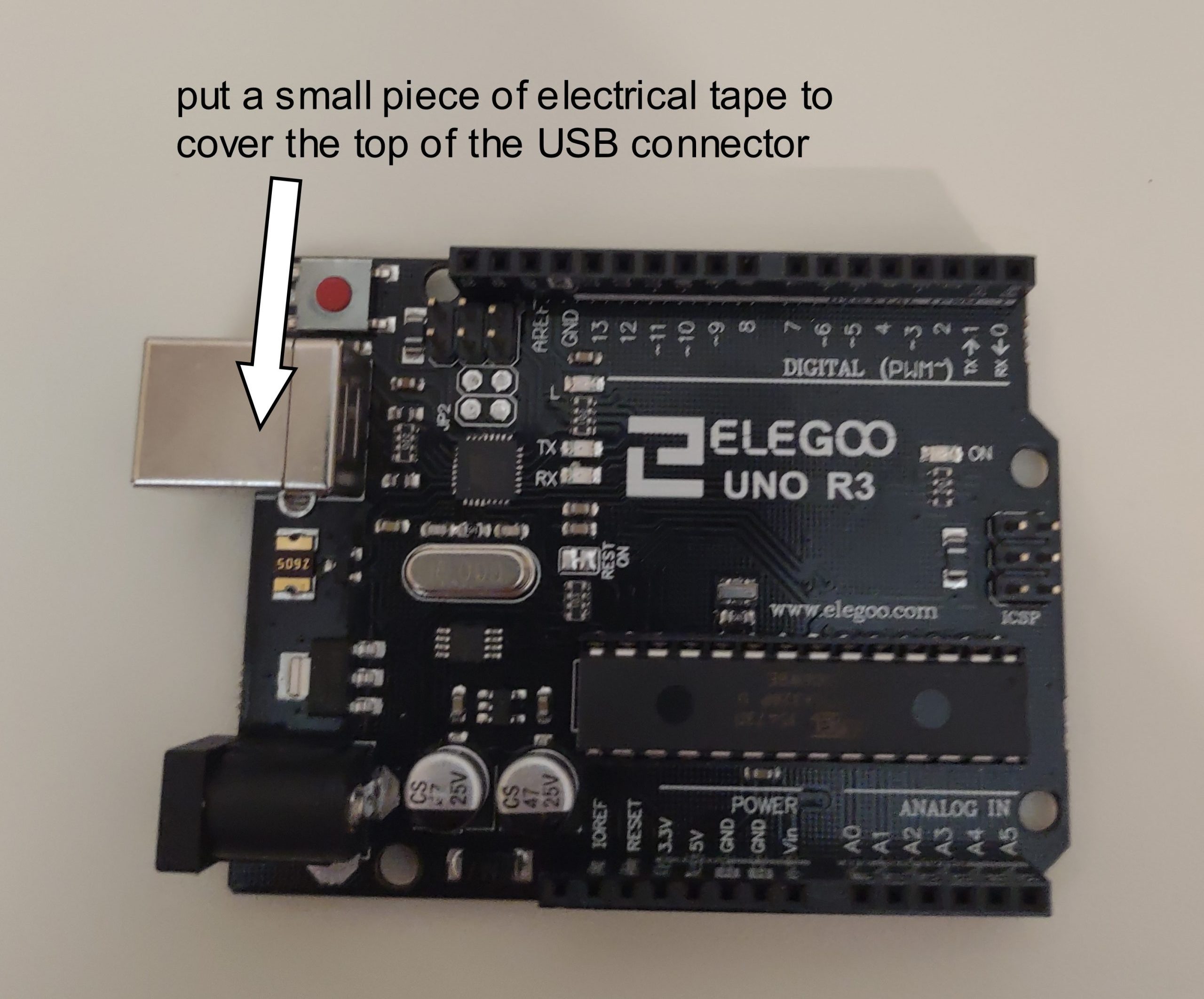
Put a small piece of electrical tape to cover the entire top of the USB connector. This helps prevent pins on the bottom of the CAN shield from contacting the connector.
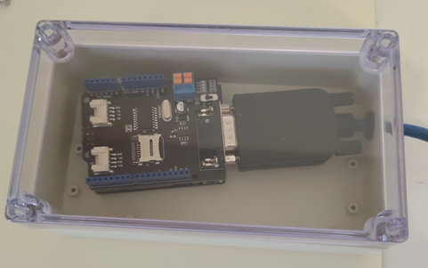
The CAN shield needs to be mounted on top of the UNO board. There is only one way for it to attach.

The finished board assembly can be secured in the box using Velcro.

Completed assembly:
Programming the UNO/ATMega2560:
It is assumed that someone attempting to construct one will have a modest knowledge of a Windows based computer. The initial work was completed on a Windows 10 based machine, but it is expected that a Windows 7 or XP based machine will also work. The computer will need to have at least 1 available USB 2/3 port.
The software for the Arduino UNO can be downloaded from here.
The download file (DEF Emulator Install Files v0.2(x32).exe) is a self-extracting file that will include the compiled Arduino software appropriate for your hardware configuration ( .bin or .hex) and files for actually programming the Arduino. It is not necessary to install any additional software from Arduino or anywhere else.
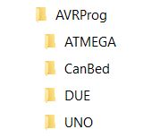
Save the file somewhere convenient on your computer. The Windows Desktop will do nicely. After the file is downloaded, just double-click the file and it will automatically create the required directory structure on your C drive and copy all necessary files into their appropriate locations. It will prompt you to verify the destination directory, just accept the suggested default. You may see warnings from your anti-virus software on your Windows computer and you may have to deal with those to allow the installation to run. The downloaded installation package will create the following directory structure in the root of your C:\ drive:
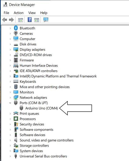
Using an appropriate USB cable, attach your Arduino board to your computer. Please note that the DUE has 2 USB connections, the one nearest the black power connector is known as the “Programming Port” and it is the one you should use. Note that the preceding sentence applies only to the DUE. Some LEDs will light up on the board showing power is connected via the USB cable. Open the Windows “Device Manager” tool and expand the “Ports (COM & LPT)”. You will need to make note of the number of the COM port being used by the Arduino. Note that the Port may also be shown as a “USB Serial Device (COM xx)”.
Close the Device Manager window.
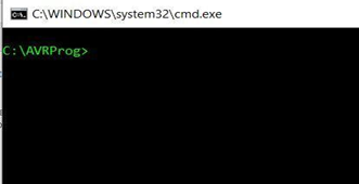
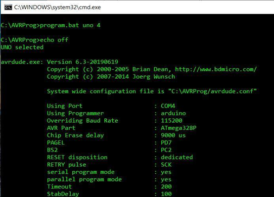
Open the Windows CMD program ( on Win10 right click the windows icon at lower left, select run, type CMD in the box and hit OK). A “CMD” window should open.
In the CMD window type: cd\AVRProg and then hit the enter key. The prompt should now indicate: C:\AVRProg.
The file “program.bat” will be used to upload the compiled Arduino software to your board. Program.bat takes 2 inputs to operate correctly: the board type and the COM port number. The board type can be UNO, DUE or atmega. You can use all upper-case or all lower-case but you cannot mix upper and lower cases. The COM port number will be 1,2,3 etc (just use the number part. Don’t type the ‘COM’ OR ’USB‘ part) that you found from Device Manager.
As an example to program a UNO on COM port 4 use:
Program.bat uno 4
For a DUE on port 3 use:
Program.bat due 3
Type the required command in the CMD window and press the “enter” key.
A lot of information will scroll by on the CMD window. As example for the UNO:
And at the completion:
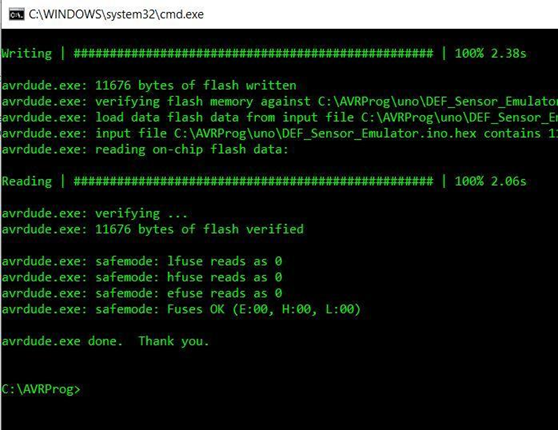
The Arduino board should now be programmed.
Connecting to your motorhome CAN network:
- Make sure that before you unplug your def head that the ignition is turned off, then unplug your def head. You may need to cut a zip tie to provide working slack in the wiring.
- Plug the simulator into the connection to your chassis wiring where the def head was plugged in.
- Turn on your ignition, some or all of the fault codes should go away and the Check Engine and MIL (Malfunction Indicator Lamp) lights should extinguish within a few minutes.
- If some codes remain, to clear your codes you will need to turn your ignition on (let all systems come up, about 20 seconds), then start your engine and fast idle for 5-6 minutes, shut down for 90 seconds, turn ignition on (wait for systems to boot 20 sec) start engine and fast idle for 5 min. You will do this a total of 3 times on the 4 cycle the codes should clear to the inactive status.
Note: on older engines or engines with older ECM software, some codes may not completely clear on their own. In this case code clearing intervention may be required. This is something that is still under study, see the Troubleshooting section for more info.

Any alternatives for the cable? The 1M cable is backordered. I guess the 3M would work? Thanks to you all!!!
Thank you for this work around! I did notice that the CAN shield and the cable connector that you spec’d are both male. Regardless, I appreciate your hard work and generosity for providing this.
Yes you are correct, it is an error in the post. The DB9 should be a female connector. I have corrected the post. Thanks for catching this
I programmed the UNO board and it seemed to go well. It said “done” at the end but unlike the example all I saw were hash marks in the window. Just wanted to make sure that is normal.
It does seem different than our experience. You saw only # and no other output?
You can attach the CAN shield to the UNO and then connect the UNO to your computer with the USB cable. Look between the boards and there should be a blinking LED if its working as expected.
Yes, only # no information. I connected as you said and had a blinking LED and other solid LEDs. So I guess it was programmed and working correctly.
I have one green light and 2 fading red lights on my board, is this right, or did I do something wrong? Any help is appreciated
Hi Jeff. If you followed the instructions for building a DSS on an Arduino “UNO” with a Seeed CANBUS shield board including cutting the P1 trace, verifying the correct USB port # and looking at your screen during and after programming to make sure that everything looks OK and there are no obvious error then you are probably good. About the only other thing you can do is to hook it up to a vehicle to verify that it does not cause any faults. Good luck
Thanks Archer, everything on the screen matched up, instructions were pretty easy, I did hook it up to my coach, I had an existing 3031 code and I thought it would clear, I ran the start and stop procedure as directed and it still remains. Any ideas?
I see the instructions are very detailed. Is anyone offering to assemble and program this for a fee? If So I would like one otherwise I don’t feel skilled enough.
Michael, the DEF Sensor Simulator is intended to be DIY project, we suggest you tap your network of friends and acquaintances for someone with the necessary skills to help with the construction.
Question about the DB9 connector for the UNO CAN Shield. The PIN numbers shown in the instructions are reversed on the DB9:
Pin 2 = ground is Pin 8; Pin 3 = CAN-H is Pin 7; Pin 5 = CAN-L is GND; Pin 9 = +12v is Pin 1.
Should we disregard the numbers and connect the wires in the same positions shown in the instructions. Thanks
I think I answered my question. I was looking at the wrong photo as I have not received the DB9 yet. I looks like the Pins in the female DB9 is as pictured in the instructions and the Pins on the male DB9 (also pictured in amazon) is reversed. Sorry.
I’m getting an error that says “This app can’t run on your PC”. It’s a Windows 10 machine, a little long in the tooth but is seems to work fine otherwise. I am running Norton security. I also tried to run it as an administrator and it didn’t work. I also tried running the compatibility troubleshooter with no luck either. Any ideas? BTW thanks for all of your hard work!
I solved my own problem. There was a little upsidedown yellow triangle by the download icon in the upper right side of the screen. When I clicked on it it allowed me to download the file. I had downloaded a -0- byte file and I hadn’t noticed it an empty file. Sorry for the confusion. Now I’m just waiting on hardware.
The DT-4 cable is backordered, is there any reason I cant just use a DT-4 kit and make up my own pigtail, I already have the crimpers for them.
Sorry for the late response. It is perfectly fine to use a DT-4 kit, we just specified the cable because it is the easiest way to go for those not electrically inclined. You can either buy the kit where you supply your own wire and crimp on the pins and assemble the connector, or you can buy a pre-assembled connector which usually has about 6″ leads then add extension wires using butt crimps which most have the tools to do.
I purchased the canbed board and I am trying to program. I have downloaded the files which show up on my C drive. I followed the instructions and the first picture of the program shows up on the command prompt. Then it says: Connecting to programmer: .avrdude.exe: butterfly_recv(); programmer is not responding. Any help would be appreciated.
Thanks
I figured out what I was doing wrong. The board shows up on COM 4 when connected. When you push the reset button it switches to COM 5. I typed : program canbed 5 and the program downloaded.
Thanks
Comment regarding Win10 for non-Win users.
I use an Apple iMac but keep a working copy of Win10 in a virtual machine for the rare occasion that I have to use it. Programming the UNO is one such case. While I’m fairly familiar with the commandline and use terminal mode frequently on the Mac, running it in Win10 threw me for a loop. MS has made it harder for novices to get in trouble running programs. First, I was using a shortcut to PowerShell and discovered that it won’t run .bat or .cmd files in the usual manner. Maybe there is a different terminal program that I should have opened.
In the VM I attached the usb cable to the running Win10 (I don’t mean simply plugging it in, you have to tell the VM to connect to it). The old style Device Manager is not easily found in Win10, in Settings you can do a search for “Device Manager” and it will show up. It found my Uno on com3 after telling the VM to attach it.
In powershell you must run .\program.bat with the required parameters for your programming of the board.
It appeared to install just fine, now I have to build it. Unfortunately, still waiting for the Seeed. Amazon had it ‘in stock’ but now it’s taking an additional week so I guess it was not in stock afterall.
Question on DB9 hookup.
I purchased the YIOVVOM RS232 D-Sub male adapter, it looks the same as the photo on this page.
The photo shows pin2 as the ground connection. This would be the ground wire from my CM2350. BUT, they terminal connection board in the YIOVVOM has a separate pin labeled “ground” which is next to pin 6.
I find this confusing, I will go ahead and connect my ground to pin 2 but would appreciate confirmation that I should use pin 2 and not the pin labeled ground on the YIOVVOM terminal board.
Thanks,
Use the instructions on this website. The DB9 connections are correct in the photo above. If you don’t mind can you send a copy or link to what you are looking at that is causing you confusion? Email to vchanko.defsim@gmail.com
FYI This will work temporarily. I have built and installed a couple on different trucks. The board does not like 14 volts that the trucks put out. Both trucks have fried the board after about a week. I am going to regulate the voltage, or buy the canbed board because it is rated for higher voltage.
I don’t doubt your conclusion but I can say that the specs on the on-board voltage regulator say that up to 20 volts for the specified part down to 15 volts for a no-name generic chip are allowed as Vin. The higher the input voltage goes though, the more power has to be dissipated by the onboard VR so if you add high ambient temps to high input voltage it could fail. Adding a switching DC to DC regulator with, say, 8-10 Vout inline in the cable ahead of the board input would probably minimize the problem.
Just for my curiosity have you tested the board on the bench using the USB connection for power? That bypasses the onboard Input voltage regulator.
can you recommend a specific dc to dc regulator for this application
Sorry, I haven’t done the research for part numbers for available Voltage Regulators but I was thinking of something in the old LM7800 family. Just needs to be able to provide anywhere from about 8 Vdc up to about 12V with at least 20Vdc input. LM7809 for instance but I don’t think those are made anymore so just find a substitute that’s similar.
I have a question about the following “Cutting this run removes a termination resistor that is not needed when connecting the simulator to the vehicle. The wire trace is connected between the blocks labeled P1 on the back side of the shield.”
Both in the picture posted above and my board I do not see that the two squares are connected, am I missing something?
Thanks so much for making this available.
First thing is to understand that this applies to the Seeed CANBUS V2 board which is the one mounted on top of the Arduino board. They come from the factory with the two squares connected by a nearly microscopic trace of copper between them. It is that tiny sliver of copper that you need to cut. The best way to know whether you have done it right is to use an ohm meter to measure the resistance between the two copper squares labeled “P1”. If the measurement is essentially zero ohms then the trace has not been severed. If the resistance between the two pads is anything other than zero then the trace is cut.
It that is too tiny to do then measure the resistance between the CAN_High and Can_Low. It should measure substantially more than 120 ohms if the trace has been properly cut.
Thanks so much for the information
I had a question about this also, on my board, which looks just like the one in the picture, those two little blocks slid right off the terminals. The picture on the build site looks like they were slid of the terminals and put back onto just one and rotated so they no longer connected the terminal thus breaking the connection, no need to cut anything. Am I missing something? I dont see any other connection other than the plastic block with the thin line that slides off.
2019 Newmar Ventana 4037 with I9 cummins on a Spartan Chassis, over the last year I have seen a lot of DEF failures posted on the Spartan chassis, I wanted to order a spare def head to carry on board in our travels but it is still on back order so I built this unit to have as a back up. Very simple to build this. I am going to do the process to also make a Blue Fire, my question is even though I dont have a DEF issue is it ok to plug this device I have built into the coach to test it?
Hi Pat. Can you clarify for me which one of the Hardware options you chose to build? I’m confused because your comment was posted in the section about using an Arduino UNO along with a Seeed CANBUS shield but the two “blocks” you are describing are only found on the Arduino DUE version from CopperHill Technologies and removing the blocks from the pins on the board is how you remove the termination resistors. It doesn’t matter whether you just remove them altogether or rotate them so they are only attached to a single pin each as long as they don’t connect the 2 pins.
On the UNO+Seeed (and the Mega 2560+Seeed) this is done by cutting the tiny connecting trace on the Seeed board. So please post with which model hardware you used and we can help.
Will this work with J1939?
Yes
Full set of DSS parts for sale, exactly as described in this Forum. Bought them for my 2016 Newmar, but have since learned it has the older model DEF sensor, so not needing to build the DSS.
Selling parts as a complete set only; all parts new in the box. Includes the Arduino UNO board, the CAN shield board, a female DB9 connector, an enclosure box, and a DT4p 1-meter extension cable. $125 shipped within the U.S.
Robert K. (Dallas, Tx)
rdk4620@gmail.com
A guy is selling a DEF simulator that reports a reduction in volume of DEF at 3% per hour. He says some other simulators don’t this which causes the ECM to think the dosing pump has failed.
I have the original build. Is this a problem?
Thanks
No that’s not a problem. That possibility was taken into account and addressed in even the very first version of the software design. There is more than one individual who are using our free hardware/software design to produce devices for sale. They often justify their asking price by claiming some improvement over the original design. In every case I’ve seen those claims are just fairy tales and the sellers have virtually zero idea of how the systems work.
The instructions say to program the uno before building it. ” It is highly recommended that you program the Arduino board before starting the assembly of the DEF simulator”. I tried to just program the board and it says something to the effect that it wasn’t found. Do I need to clip the wire, flip the switch and put it together before programming it?
Your message says “…program the UNO…”, My question is are you sure you have an UNO board? UNO is a specific variant of the general term Arduino and refers to one of several possible boards that can be used but the UNO is a very old hardware platform and I haven’t seen one in a couple of years. In the early days of the DSS the original recommended hardware became scarce and expensive and the UNO was cheaper and available but was never very good. They were hard to assemble and lacking in capacity.
There are several versions of Arduino platforms that have been recommended with the most current and highly recommended one called the CANBED RP2040 available at this link:
https://www.digikey.com/en/products/detail/seeed-technology-co-ltd/102991596/15976345?s=N4IgTCBcDaIIwFYCcB2AtHADGJTFIDYQBdAXyA
If you really do have an Arduino UNO you would be way better served by just getting the RP2040 instead and use the instructions for that board. All the other components like enclosures, connector, cable, etc can still be used.
If you just misunderstood and do, in fact, have the RP2040 board then use the proper instructions to program it. The RP2040 is only about the size of a credit card and has two pushbuttons on the board. It is MUCH MUCH easier to program than any of the predecessors.
Note that each type of hardware required a different procedure to program it so it is critical that you use the right instructions.
Sorry it has been a while since I tried this but trying again now with no luck. I go thru the whole process but when it tries to program it keeps saying not in sync. Programmer not responding. It does that ten times and then says finished. Yes I have the Uno and the shield on it that I had to clip the little trace wire. Not sure what I am doing wrong.
Thanks for the help!
Dennis, check your email. I sent you a message asking that you reply via email with your phone number so I can call and work out whats going on.
Vic Chanko
I have reviewed comments on this DEF Sim being for CM2350 ECM and as of Sept. 2021 it stated this program has not been tested on the CM2250 ECM. My question is: has there been any further testing of this program to determine compatibility with the CM2250. This is concerning a 2012 Winnebago model coach with a Cummins engine.
Hi Lawrence, your 2012 model Winnebago with a Cummins engine does not use a digital 3-function sensor (ie a sensor that measures Level, Temp and QUALITY of the DEF).
Your sensor is an analog device and is not prone to the excessive failures that have been experienced by the 2016 and newer engines.
Therfore your question about the CM2250 ECM is moot. Your coach is NOT a candidate for being able to use the simulator at all.