DEF Sensor Simulator – CanBed ATmega 32U4
Assembling a DEF Sensor Simulator Using a CanBed ATmega 32U4
Only basic electrical and DIY skills are required for the hardware assembly, however some basic soldering is needed to install the 4 pin connector. There are many YouTube videos that can teach you to solder. For delicate electronics such as this use a low wattage grounded soldering iron (25 – 30 Watts) to help prevent pad damage, don’t use a soldering gun.
The software installation in this procedure can be done from Windows and is relatively straightforward.
Before you begin, please click here to read an important compatibility notice regarding the ECM (Electronic Control Module, aka Engine Computer) and info on compatible DEF head connectors.
If you run into difficulty post a comment at the bottom of this page.
Please read through all the instructions FIRST before beginning the project. There are web site links embedded in the instructions to help obtain parts.
NOTE: before mounting in the enclosure box, the CanBed needs to be programmed! Please see instructions in the Programming section.
Tools:
• Drill & bits
• Wire cutters / Strippers
• Small screw driver
• Ohm meter (multi-meter)
• Silicone sealant (optional)
• Soldering iron & solder
Parts list:
1) The CanBed board can be obtained from several online sources. This board has the ATmega32U4 processor. The suggested source is Digikey.com p/n: 1597-102991321-ND
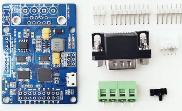
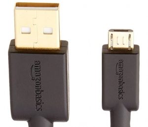
2) You will need a USB cable with a micro USB connector, as the board does not come with one. They are available at online retailers or in many stores. Here is one from Amazon.
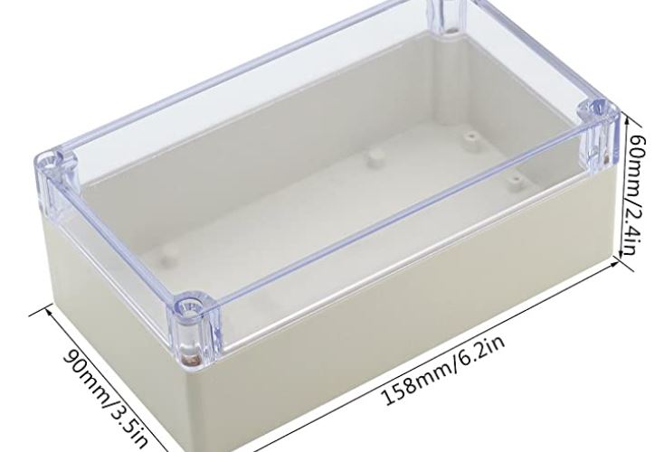
3) Weather tight enclosure. The entire assembly of the CanBed is very small. The enclosures used on the UNO or DUE variants will work just fine, although they are larger than needed. Feel free to get a smaller one if desired. Here is one from Amazon that will work.
4) The cable and waterproof gland nut (shown in Quick Start section of main page) used on the DUE assembly can also be used with the CanBed.
As an alternative to the “Gland nut” you can use a rubber grommet, which can be purchased from most hardware stores, such as ACE Hardware. Just get one that will fit your cable diameter. You could also just fill the hole in the box where the cable goes through with silicone sealant.
Assembly:
It is recommended that you program the CanBed board before doing the assembly. Please refer to the Programming section at the end of this post.
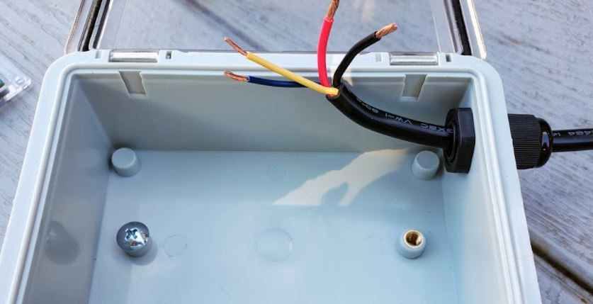
Take the 1 Meter DT Extension cable that you purchased and cut the off the flat end with the exposed orange silicone as shown in the picture below, approximately 4 inches from the connector. The short end with the Orange silicone connector will not be used electrically, but if desired can be used as a “dust cap” for the DEF head sensor connector when the DSS is not in use.
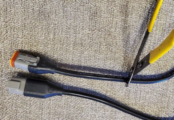
After cutting the cable, trim back the outer jacket about 4 inches and expose the 4 inner conductors. Be careful to not cut the inner conductors.
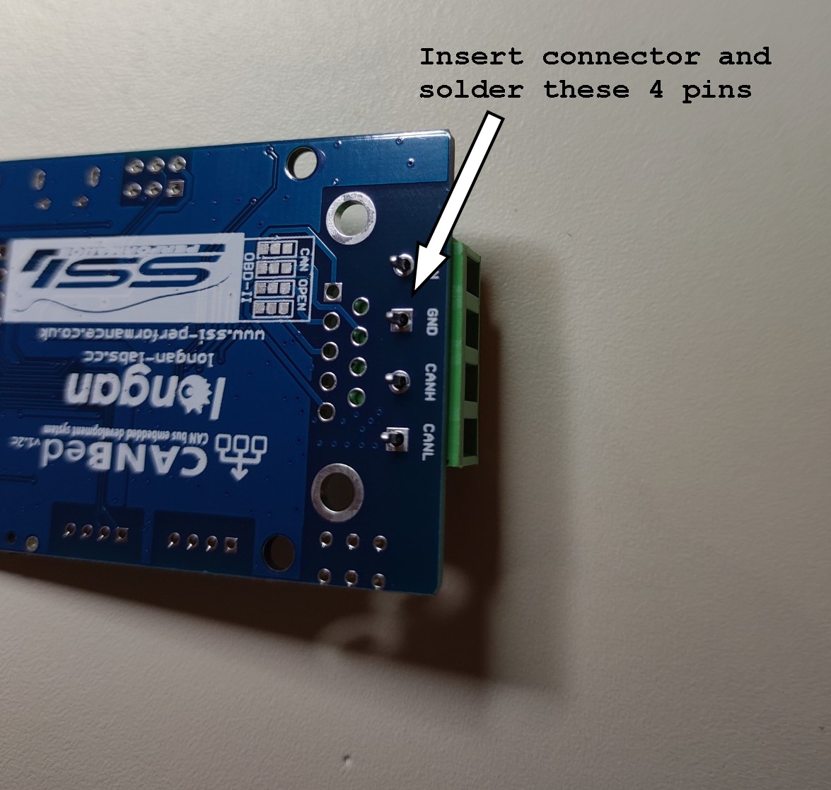
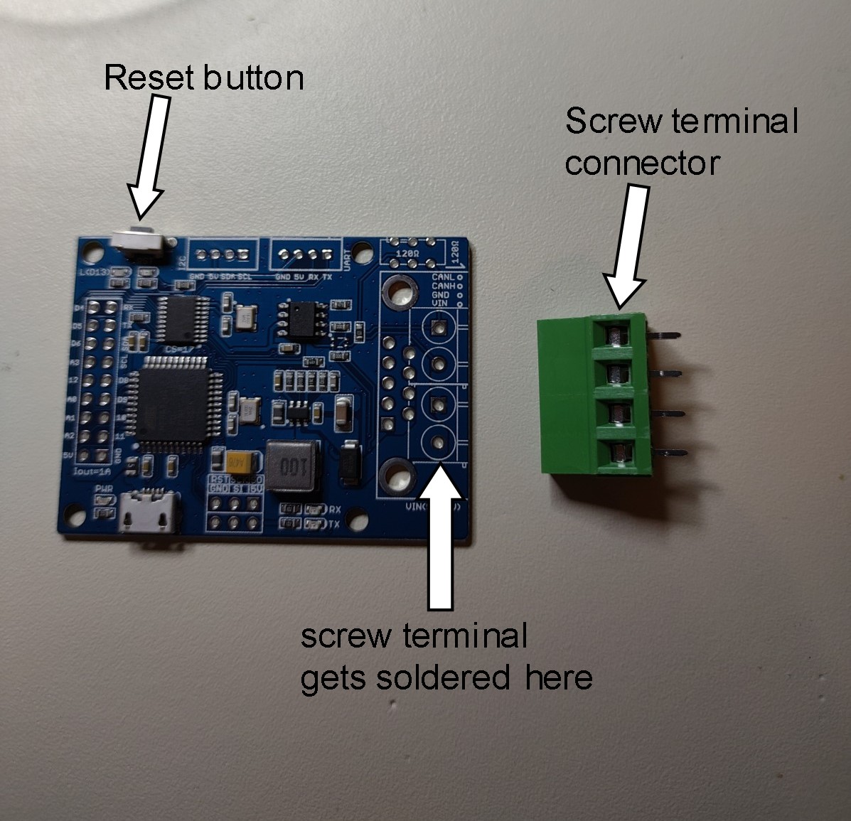
As noted at the beginning, the CanBed needs to have a connector soldered to the board. The connector comes with the board. You can get a very inexpensive soldering iron kit from Amazon (see tools list )
You can optionally directly solder the cable wires to the board if you wish. If you choose to solder the wires directly, you will need to feed the wires through the enclosure first.
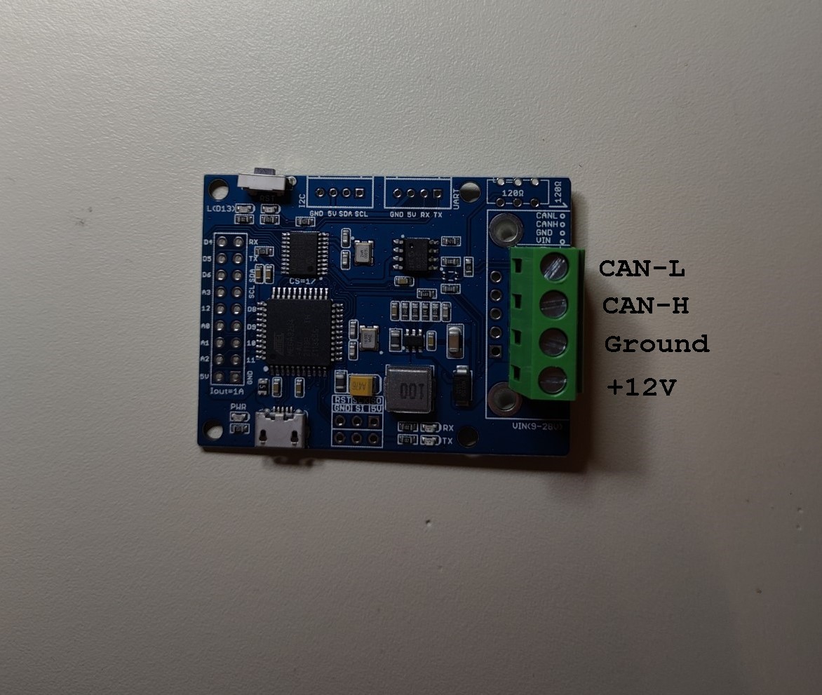
The wiring connections on the 4 pin DT04 connector are: +12v, ground, CAN-H and CAN-L.
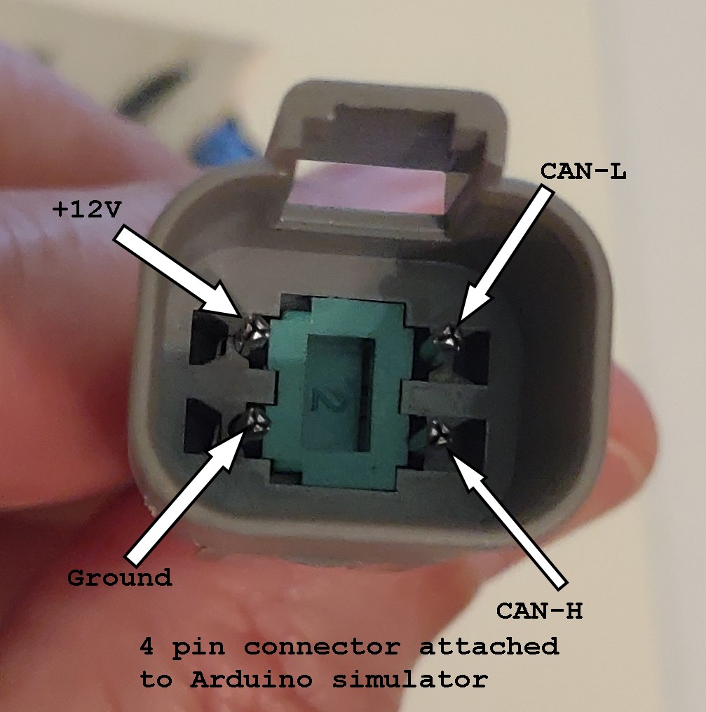
The wires associated with these pins (above picture) are connected to the CanBed via the screw terminals. You will need to use an ohm meter (multi meter etc) to determine which wire is connected to which pin, as the wire color codes are not standardized.
Drill a hole through the enclosure to accommodate the cable and gland nut (or grommet, whichever you are using). Feed cable into enclosure.
Strip about 3/16 inch of insulation off each wire end and connect to the screw terminals. Make sure the slot is fully open as shown in the picture below. If the wires are too large, you can trim off a few of the strands. Make sure there are no loose strands sticking out of the connector.
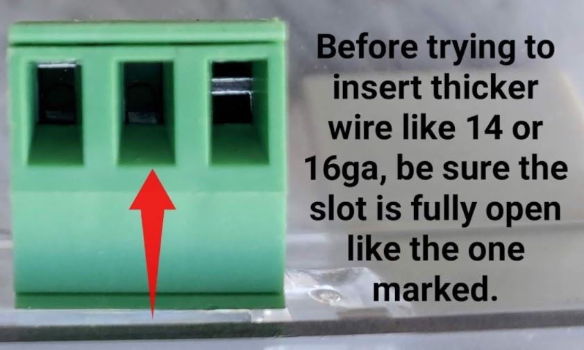
Insert the stripped wires into the slots shown in the picture below:
Tighten the screws to securely fasten the wires in the slots.
The finished board assembly can be secured in the box using Velcro.
A completed assembly:

NOTE: before mounting in the enclosure box, the CanBed needs to be programmed! Please see instructions in the Programming section if this has not been completed.
Programming the CanBed:
It is assumed that someone attempting to construct one will have a modest knowledge of a Windows based computer. The initial work was completed on a Windows 10 based machine, but it is expected that a Windows 7 or XP based machine will also work (USB drivers could be an issue). The computer will need to have at least 1 available USB 2/3 port.
The Arduino software install file can be downloaded by clicking here. The full github page can be viewed here.
When your browser opens to the page, click on the “download” button to download the file.
The download file (DEF Emulator Install Files v0.2 (x32).exe) is a self-extracting file that will include the compiled Arduino software appropriate for your hardware configuration and files for actually programming the Arduino. It is not necessary to install any additional software from Arduino or anywhere else. The browser will typically download the file into the “Downloads” section as shown in Windows File Manager.
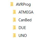
After the file is downloaded, just double-click the file and it will automatically create the required directory structure on your C drive and copy all necessary files into their appropriate locations. It will prompt you to verify the destination directory, accept the suggested default, which is C:\AVRProg. You may see warnings from your anti-virus software on your Windows computer and you may have to deal with those to allow the installation to run. The downloaded installation package will create the following directory structure in the root of your C:\ drive:
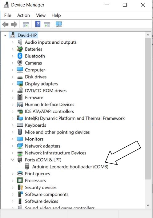
1) Using a micro USB cable, connect the CanBed board to your computer’s USB port. You should see a LED light up next to the micro USB port on the CanBed board. This indicates power to the board.
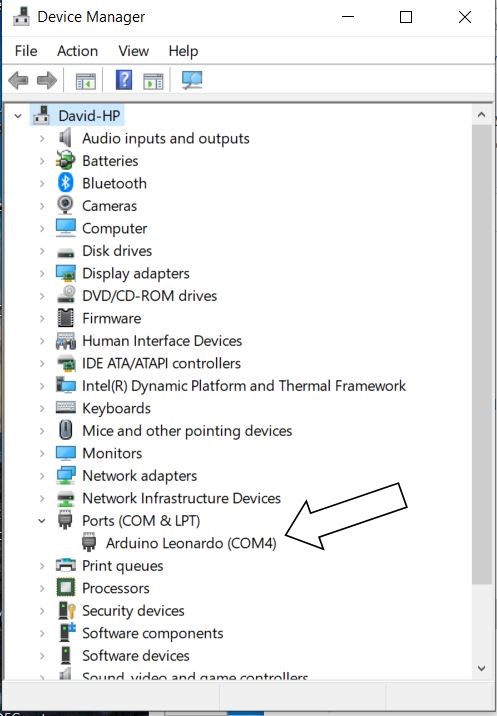
2) Open Windows10 Device Manager (right click on windows “start” icon in lower left of screen and select Device Manager). Look under “Ports (COM & LPT)” and you should see the board listed. Note that it may be only listed as “USB Serial Device”. Here it’s shown as COM4. If there is more than one device shown, unplug the CanBed board and see which device is removed from the list. Be sure to plug the board back into the USB port.
3) Leave the Device Manager window open. Press and release the reset button on the CanBed board.
4) Watch for the Device Manger window to refresh. Under the Ports section you probably will see the COM# value change. Note this new value. Make sure the COM# does NOT overlap with another COM device.
5) Open a Windows10 CMD window by right clicking on Windows “start” icon at lower left of screen and then left click on Command Prompt.
6) Type: cd\avrprog and then hit Enter key
7) You should see the command prompt as C:\AVRProg
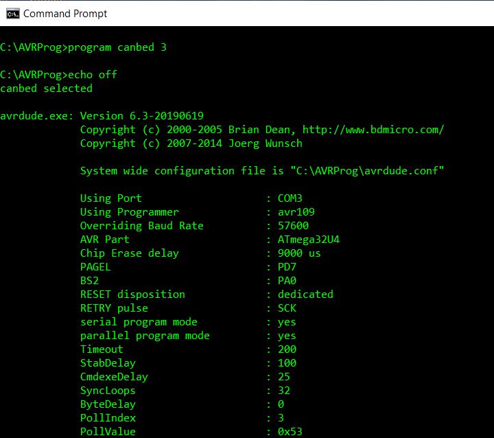
8) Type: program canbed x where x is the COM port number (1, 2, 3 etc) from step 4. DO NOT hit Enter key yet!!
9) Press and release the reset button on the CanBed board
10) Wait about 2 seconds and then press the Enter key in the CMD window
11) You should see something similar to this:
And when finished:
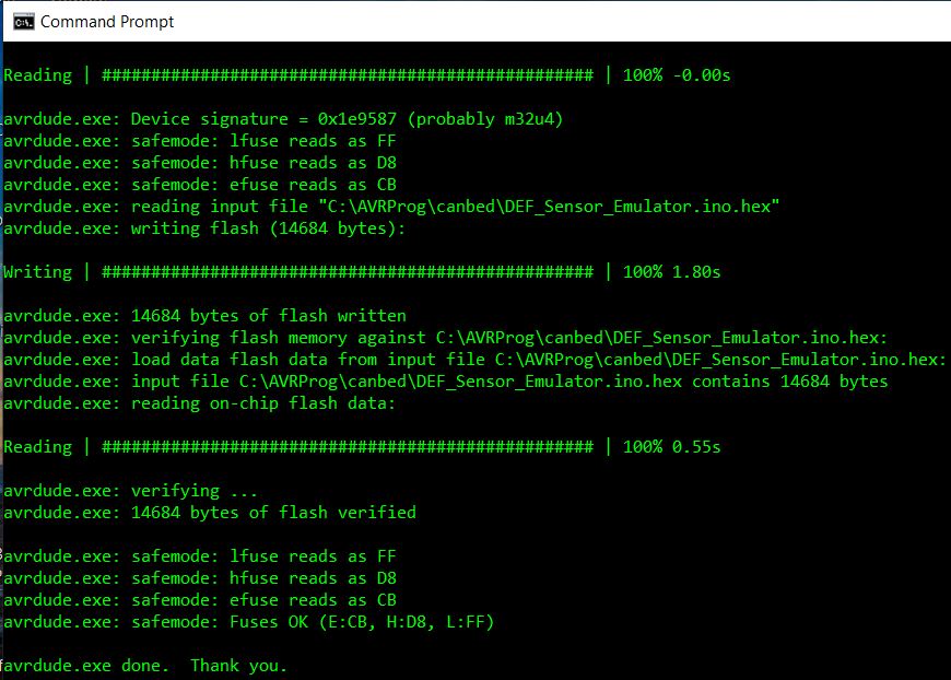
12) Programing is now finished.
After programming, it is expected to see a LED behind the reset button double flash about once per second. You can now disconnect the board from your computer.
Video after programming:
Connecting to your motorhome CAN network:
- Make sure that before you unplug your def head that the ignition is turned off, then unplug your def head. You may need to cut a zip tie to provide working slack in the wiring.
- Plug the simulator into the connection to your chassis wiring where the def head was plugged in.
- Turn on your ignition, some or all of the fault codes should go away and the Check Engine and MIL (Malfunction Indicator Lamp) lights should extinguish within a few minutes.
- If some codes remain, to clear your codes you will need to turn your ignition on (let all systems come up, about 20 seconds), then start your engine and fast idle for 5-6 minutes, shut down for 90 seconds, turn ignition on (wait for systems to boot 20 sec) start engine and fast idle for 5 min. You will do this a total of 3 times on the 4 cycle the codes should clear to the inactive status.
Note: on older engines or engines with older ECM software, some codes may not completely clear on their own. In this case code clearing intervention may be required. This is something that is still under study, see the Troubleshooting section for more info.

I keep getting a message while trying to program board that butterfly_recv() programmer not responding
Hi. I’m having the same problem with programmer not responding. What’s odd is, my COM port does not changed when I reset – it is always COM3. It flashes twice, but shows COM3 every time. For giggles, I tried programing to COM2 & 4 – but get an immediate cannot find file… Any ideas? Thanks!!
Hi Skip. Check your email for a message from VChanko.defsim@gmail.cơm with a request.
So built this solution and it worked perfectly. Was so economical I purchased and flashed 2 boards so I had a backup board just in case.
I HAVE NOT had any issue with my sensor as of now but wanted to have this as insurance just in case it happens.
A HUGE THANK YOU! To all that contributed to this project.
I did notice that the link for the canbed has been lined out, I was wondering what that’s about.
Hi Steve,, Might you of built a extra or two?? for those of us electronically challenged and now DEAD at a rv park waiting for DEF problem repairs?
Would u b interested in building me one of these. Im will to pay$100
Hi. I am trying to program the CanBed solution and getting an error as follows.
Connecting to programmer: .avrdude.exe: butterfly_recv(): programmer is not responding
Not finding much help for my particular problem so far. Looking for some hints.
Please follow the instructions carefully especially Steps number 3 & 4 AND 8 thru 10. The board uses a different USB COM port number during programming than the one that Windows initially assigns. You must use the “Reset” button to force the board to switch to the alternate port number that you determine in steps 3 & 4. This is 90% of the problems that users are reporting, the other 10% are trying to use a USB “charging” cable which does not have all of the internal wiring connected end-to-end.
Hi Archer, Just picked up my 2022 Newmar Kountry Star reading def head problems is scary. How do I know if I have the effected heads? If I do and attempt to build the canbed the digikey # listed above is crossed out? Why?
Thank you for all your help and knowledge that you guys share with us.
Hi Chris. Unfortunately no one knows why the DEF Sensors fail for sure. Nor does anyone know which iteration (Shaw is currently on generation 7) is more or less prone to failing. Your new coach may last a lifetime without any DEF Sensor problems. On the other hand it might suffer a failure driving home from the dealer. Nobody knows.
My advice, and it is just my opinion, would be to first verify which of the two known connector designs is used to connect your OEM Sensor to the coach wiring harness (ie the Deutsch DT4 used on Spartan chassis or the TE black and yellow connector used on Freightliner chassis) so you order the right connector. Then I would source the CanBed board from Digi-Key as well as the enclosure, etc and then build and program it. Just put it away in case you ever need it and enjoy your new coach.
The Digi-Key link works just fine. VoltDoc tells me that it’s just some minor issue with the WordPress software. Your total cost should be well under $100 all-in.
Another thing, here is an Amazon link to an enclosure that works well for the CanBed board and includes the waterproof gland nuts/strain relief.
https://www.amazon.com/VONVOFF-Electrical-Waterproof-3-27×3-19×2-20-83x81x56mm/dp/B08Z36YL1N?pd_rd_w=Lw0ZB&pf_rd_p=bb77d25e-38d7-4c74-a263-e922267edaaa&pf_rd_r=RH8GA7JPGSX3KCQM601W&pd_rd_r=f3ca468a-e72a-4e4a-b351-5e73273fc311&pd_rd_wg=nGfNY&pd_rd_i=B08Z36YL1N&psc=1&ref_=pd_bap_d_rp_1_t
My board appears to be programmed. Received the ok message. There are now 2 red LEDs lit on the board. Is this a problem?
If you are talking about the two tiny LEDs labeled Tx/Rx then yes, they will both be lit. When the DSS is connected to a live vehicle J1939 CANBUS they will flicker rapidly as data is sent and received.
thanks. They are TX & RX. solid red now after programming. Not hooked up to anything as I’m waiting for the cable.
Where can we get a cable that is not a charging cable?
Hi Archer, I have followed all of the above steps very closely and bought the USB cable that is in a link from the write up and I continue to receive the error message “butterfly_recv(): programmer not responding”. When I enter the path into the command window, I do get all of the information as illustrated in your first screen shot above but not the second screen shot. I have tried a variety of usb cables but none of them see the board. The cable I bought from Amazon from the link above see’s the board but doesn’t respond. The box the cable came in from Amazon does indicate it is a charging cable. Maybe we have a bad link to that cable by chance?
The Amazon site does list this cable as being a data transmission cable.
Hi Dennis. Re-read the Programming instructions very carefully. In Step 3 and 4 you should see the port number change for about 5 seconds then it will revert to what ever the initial port number was. You need to make note of what the temporary port number was before it changes back. For instance, you plug the board up while watching Device Mgr. And you see the board connect with a Comm port of (for instance) 3. Then press & release the reset button on the board and observe the board disappear from the list then reappear as com port (for instance) 4 then the process will repeat by itself and reconnect as 3 again.
Now when you type in “program canbed X” use the temporary number (in this case) use 4 NOT 3. Then push and release the reset button on the board, count 2 seconds and THEN push the ENTER key to start the programming.
This is all documented in steps 3 and 4 AND 8-12.
IMPORTANT MESSAGE:
To anyone who is getting an error when trying to program the CanBed that says something like “Connecting to programmer: .avrdude.exe: butterfly_recv():…” go up to the “Programming” section and pay close attention especially to Steps number 3 & 4 AND 8 thru 10. The board uses a different USB COM port number during programming than the one that Windows initially assigns. You must use the “Reset” button to force the board to switch to the alternate port number that you determine in steps 3 & 4. This is 90% of the problems that users are reporting, the other 10% are trying to use a USB “charging” cable which does not have all of the internal wiring connected end-to-end.
Please help. trying to build two of these for a family trip, one for me and one for a family member. Keep getting the butterfly error and can not connect to the programmer. Any assistance will be greatly appreciated as wife will not travel till I get this done. Obviously I am under zero pressure here.
Rob. Check your email for a message from vchanko.defsim@gmail.com
Hi Archer,
I have the Digikey Arduino and have verified the comms port, changed cables, when resetting the Arduino it takes longer than 2 seconds on my Win10 laptop is goes to 8 then back to 7 after a few seconds.. I do the program canbed 7 and continuously get Connecting to programmer: .avrdude.exe: butterfly_recv(): programmer is not responding
avrdude.exe: butterfly_recv(): programmer is not responding
I fly out from California next Friday 3/18 to Tennessee to pick up our 2019 RV with a Cummins in it (which has already had the def had replaced once).
I am hoping to have this little guy with me in case any issues on our 2400 mile trip home.
Thanks
Greg
Hi Greg. Check your email.
followed the steps, kept getting avrdude.exe butterfly_recv(): programmer is not responding. I did get pass all the hardware reading prompts. Tried multiple USB cables but still no luck. Please Help
I Sent you an email with some more info.
I’m getting this same issue and the one mentioned above where it changed numbers then changes back. I’m leaving in the morning for a 10 day trip.
Marla
Hi Marla, check your email for a message now.
The datasheet for the CanBed board does not list the board dimensions. Has anyone found a document with the board dimensions?
The board is 56mm X 41mm or about 2 1/4 x 1 5/8 and with the terminal attached about 1 inch thick
Thank you!
Just finished programming my board. Great directions! Just one thing to note, in case some others, with limited Windows knowledge, have the same situation. My Windows 10 computer has a Windows Powershell instead of a Command Prompt. It works the same, for this application, with one exception. Instead of typing program canbed x, you need to type ./program canbed x
The ./ simply tells Windows to use the current directory to find ‘program’. I guess it is a safety feature of the Windows Powershell.
Thanks to all who spent their time on this great tool. I will feel much less stress on our next RV trip.
Good catch! Thanks for sharing the tip.
Thank you for putting this out there. I just completed the build but haven’t had a chance to test it out yet. No issues with the programming.
I had a couple questions about it- what will the sensor values be defaulted to? Is there any way to change the “temp” or “level” in the programming using arduino?
The answer to the first question is that on each startup the DEF level will be forced to 75% and will drop by a small percentage each hour that it’s on. The DEF temp starts at about 75F but then switches to whatever the ECM is reporting as ambient temp. The switch occurs as soon as there is valid data from the ECM. THE DEF quality is defaulted to 32.5% and does not change.
The answer to the second question is since we will ONLY distribute the compiled binary run-time there are no user-defined variables.
Gotcha. The temp might be problematic for folks when its cold as you would get a DEF frozen fault. The coolant will be allowed to warm the tank but the ambient temp will stay cold never allowing the engine to come out of the derate…But you can’t have it all.
Can you recommend any good material or resources for learning more about how to build/program CAN emulators like this? I have seen a few “boxed” programs out there.
You are correct about the temp sensor. This device is meant to be a do it yourself way for an RV owner to be able to get to a safe place to get a permanent repair done. Not many RVs are used when temperatures get down to 12F where the DEF freezes. If you really needed to add an external temp sensor to your project one of the developer/programmers might agree to write and compile you a custom version to support something like a DS18B20, but I doubt they would do it for free.
Is the Digikey part number not valid, if so do you have a suggested alternative?
Yes, the link is still valid. There is some kind of WordPress situation that causes it to have a strike-thru. I just ordered 2 of the Seeed CanBed units using the link and got them in 2 days via FedEx Economy.
I am in the process of ordering the parts, but noticed that programing required a Windows computer. Can an the device be programed using a an Apple computer?
Thanks for your work on this issue.
We have parts coming next week to include Canbed board. I don’t see anywhere in the instructions that we need to disable termination resistors by removing jumper wires like the other boards. Can you confirm please?
The CanBed board comes already configured WITHOUT any termination resistor. But just in case somebody might need for it to be terminated, it comes with a tiny slide switch that can be soldered onto the board to allow for the terminator to be switched in or out of the circuit. This switch is NOT necessary for 99.99% of users.
Thank you
I just assembled it.. Great job on putting this out there. I have not tested yet. I did run into two thing that don’t quite match the instructions..
1. I’m getting two quick blue flashes near the rest button after programming. Even when hooking up 12V and ground on a bench test. The instructions state one flash per second.
2. I had to download the IDE to get the drivers installed. https://www.arduino.cc/en/software. I am on a windows 8.1 machine.
Thanks for the input. Glad you figured out the driver thing. We weren’t able to test every version of Windows and rarely does this happen but sometimes it does.
As to the blue flashing, if it were music it would be “2 eighth notes, quarter note rest, 2 eight notes, quarter note rest” @ 120 bpm. (Counted 1& 2 3& 4)
I am seeing the same double blue flash as described above. The result is the same as in the picture above.
Do you know what I am doing wrong?
Hi Randy. Check your email account. I sent you a video of a properly functioning unit. I’m not clear what you are asking but the double blue flash is normal. What “picture above” are you referring to?
Another question Britt, did you just download the Arduino IDE with the standard, default libraries or did you also need to go to Library Manager and search for a particular library and add it? If so which library did you add?
OK, I need help. I put Windows 10 on my Mac and downloaded the software file. When I double-click it to store on C: drive, it shows the correct place like in the instructions, then I click next and nothing happens. I went ahead and connected the board and went thru everything to the point of typing commands in the Windows Powershell and it couldn’t find the file. I’m not real proficient in Windows so anything you can provide is appreciated.
Vic: You are the man; thanks so much for helping us set up the board. It was nice chatting with you too!
I have built both the Arudino UNO version and the canbed version. I connected both to a Raspberry Pi with a CAN HAT in order to test. When I do a candump, I see slightly different messages from the two versions (first byte in second message). Both alterate between two different messages.
Canbed:
$ candump can0
can0 18FE56A3 [8] BB 3D 94 09 FF FF FF FF
can0 18FD9BA3 [8] 3D 82 FF FF FF F3 FF FF
…
Arduino Uno:
$ candump can0
can0 18FE56A3 [8] BB 3D 94 09 FF FF FF FF
can0 18FD9BA3 [8] FF 82 FF FF FF F3 FF FF
…
Is this expected behavior?
Thanks,
Kelly
It depends on when you programmed your UNO. When the CanBed was released, there was a minor update to all versions to include temperature in byte 1 of PGN64923. If you download the most current code and reprogram your UNO, I would expect both to have the same output.
Thanks – that would explain it.
OOPS
I built two can beds. Does it matter electronically which side I passed the screw terminal connector. one is correct the other I passed through the opposite side of board
No, as long as the connectors pins are soldered to the board it doesn’t matter whether the connector is on the component side or the solder side. Be very careful, of course, to verify that you sort out which terminal port is Can High, Can Low, +12V & Ground and connect them to the wiring correctly.
Vic
Thank you for validating my oops.
Excellent tool. With the “Shaw Development” sensor arrays failing at alarmingly high rates and Shaw’s inability to source parts to build replacements this is a lifesaver, literally. As info, the Seeed CANBed fits perfectly into an “On!” nicotine pouch container and can be waterproofed with your choice of potting or hot glue. Thanks for making it so that we can get equipment moving again, out of the way, and to somewhere safe. I would add that I struggled with instruction #9. My computer would recognize the bootloader on “port 5” and then after 6 seconds revert to “port 4” for the Arduino. It’s been clarified above, but you want to program it during that 6 second window on the “port 5” (or whatever port yours picks for the bootloader) before the windows machine makes the second ding and reverts to “port 4” (or whatever yours chose).
Good to hear from you. Congratulations on your success, you are a SuperStar! Now that you’ve mastered the DEF Sensor problem can you help out a little with this Covid thing?
Thanks.
Kidding aside, what kind of “equipment” are you dealing with? So far the most exotic uses I’ve heard about have been for a construction forklift and a hydraulic seeder.
This instruction is great and very easy to follow. I had no problems programming the adapter and completing the build. THANK YOU for putting in the effort to document everything and make it available to us.
Everything for the build went as advertised. I plugged in the simulator to test it and I got the following codes.
SPN 729
FMI 5
It appears this is a random coincidence as this code is for the intake heater. A search shows that this is somewhat common fault.
Anyone had this happen and do you think it could possibly be related to testing the simulator?
Just a coincidence. I don’t think it is even a fault code per se. I believe it’s just an advisory that the ECM has called for activation of the Inlet Air Heater Relay.
Looks like your DSS test was successful or you would have gotten a whole different set of faults.
Congrats
Thanks, I thought so. No other lights so I guess the test is good. Just had my head replaced but not I have peace of mind if it happens again.
I cut the cable with the DT04 connector. When I measure the pins using the picture of the connector above ,I get the following result:
+12V Yellow
GND Blue
CAN-H Black
CAN-L Red
The red and black wires are thicker in diameter and the colors above are not in line with CANBUS specifications. CANBUS specifications are:
RED 12V
Black GND
Yellow CAN-H
Green CAN-L
The CANBUS specs make more sense to me with red and black (thicker wires) for power.
Before I connect my board, I want to make sure that I get this right. Anybody with the same experience? Any advice?
I am assuming that you got your cable from Diode Dynamics. This cable was just specified because it came with the right DT04 male connector already professionally assembled. Unfortunately this cable is actually intended for use in automotive LED lighting effect systems, not CANBUS applications, so the wire colors have no relation to the standard CANBUS signal wiring specs.
So you should use the instructions on this website in assembling your DSS project. The instructions also recommend that you trim some strands from the red & black wires to make them easier to fit into the board screw terminals as the wire gauge is way heavier than actually required.
Good luck
Thank you for your quick response and the clarification. You are correct that I got the cable from Diode Dynamics. Then I’ll follow exactly the instructions above! Thanks again Frank
We have a 2015 Tiffin Phaeton with a Cummins ISL380 engine. The sensor on top of the DEF tank has a 5 wire connector. Are there any plans/instructions for a 5 wire connector on the sensor/simulator?
Hi William, Happy Holidays!
Your DEF Sensor is an analog device and works entirely differently than the post-2016 units that have been plagued with the sensor failure/ECM derate. As we have said before, it’s not just a question of the connector type (unlike the situation with post-’16 Freightliner chassis where the sensors were functionally the same as the Spartan and just needed a different type connector).
So, no, there are no plans for any kind of DSS for your situation. But the good news is that your coach is not vulnerable to having the same problem that the DSS was designed to relieve.
followed the required steps, keep getting “avrdude.exe butterfly_recv():programmer is not responding”. Passed all hardware reading prompts. Tried multiple USB cables and two different boards but still not able to download to card. If I send you the cards can you program for me and I will pay for your time?
Curt. Check your Gmail account. I sent you a private email message
Thank you, Mr. Bland, for the assist in programming our CanBed cards. Frustration level since subsided.
I completed the build. Actually is very easy but did have some trouble with programming the Canbed card as I did not understand the desired port was the temporary port. Once I got that, programmed just fine.
Was testing the unit and fault codes 1761 & 3031 came up. I have a 2018 Aspire with the ISL 450. What do I do to correct this.
Thanks in advance for the help.
Hi Steve. The fact that you got the errors (which are 2 out of 3 of the same codes you’ll get with an actual DEF Sensor failure) is almost certainly due to a problem with the wiring. Either a loose connection or two wires shorted at the board end or you have made an error in how the wires from the connector are connected to the board. Less likely is that you didn’t get the connector between the DSS and the coach wiring harness fully seated.
As far as clearing the 2 codes, assuming your OEM DEF sensor is functional, just plug the OEM sensor back in and turn the key on. The codes should clear themselves either immediately or after 3 consecutive start/idle cycles of 5 minutes each.
Thanks for the quick response. Cycling the engine 3 times cleared the codes. I checked the wiring and can’t see anything wrong. Put the unit back in and got the same codes. I can’t attach a photo of the box and wiring. If you can send me your email address I can send you a photo.
Thanks
Will this emulator work on Paccar MX as well or just Cummins?
I just build a CanBed Unit. thank God I order 2 boards
One of them has a short in it. and its messing up my USB ports on my different PCs
confirm its a short becuase some thing on the board its getting really hot.. THis is just with the usb from board to PC, didn’t even do any thing else
lucky the vendor was great and the yare sending me another one.
I successfully program the 2nd unit. and will be testing it today on a
2015 International Pro Star with a cummings engine.
lets see if it works
Hi Armando, are you sure that your truck uses a DEF tank sensor with all 3 DEF parameters? Temp, quantity AND concentration (32.5% Urea concentration)? The systems that are compatible with the DSS are generally 2016 and later.
Have you verified that your OEM sensor has either the rectangular 4-pin Deutsch DT04 or the “Freightliner-style” black and yellow TE Connectivity connector?
I’m not saying the DSS WONT work but I don’t know whether it WILL as I don’t know whether anybody has ever tried.
Yes , it worked, and yes it has the 4 pin DT04 connector.
Tested it this morning, truck registered 75% def, all codes clear, and no longer in Derate mode. Yeah, Im note sure why this 2015 model has the Digial Sensor, instead of analog.
Awesome, good for you and thanks for letting everybody know.
Will this work with a 24 volt system.
The Seeed Studios CanBed board specifications say that it is good for 9VDC-28VDC. The DUE with extended power option from CopperHill Technologies claims it is good for 7VDC-36VDC.
I couldn’t find the spec for the Arduino Mega2850 and Arduino UNO with the Seeed CANBUS V2 interface so I don’t know whether it would work at 24VDC but my memory tells me that it would probably NOT work. Son the answer depends on what hardware platform you are using.
Good luck
I see a majority of failures/complaints with the Spartan chassis, although I know they have occurred on multiple. I have a 2017 Newmar Ventana 3412 on a Freightliner chassis. As we are making the jump to Alaska this year (Canada border crossing compliant), I’d be nuts not to carry a simulator with us. Since the coach is in storage, I haven’t laid eyes on the connector interface yet. My question is whether I can expect any different connector (4 pin DT04) on the Freightliner chassis vs the Spartan, or any other variations for that matter?
I would assume that your Ventana would have the TE black and yellow connector, not the Deutsch DT04. You should verify which connector your coach has before you build the cable or you could fairly easily build the device with one of the two possibilities and then fabricate a female to male adapter pigtail and cover all the bases.
Can I program the board on a Apple computer?
Hi all, hope you can help me. I recieved my CANbed board today and before I did anything to the board, I am trying to program first. I doownloaded the software and read the instrutions carefully. Once I run the program command I get this message
avrdude.exe: ser_open(): can’t open device “\\.\COM8”; The system cannot find the file attached
avrdude.exe done. Thank you.
What am I doing wrong ? Please let me know… Thx, Bill
Hi Bill, check your email for a message from Vic Chanko. The short answer is re-read the programming instructions. Pay special attention to steps 3 and 4 and 8 through 12 regarding the port number and when to push the reset button. The board uses the temporary port number for programming and has to be forced to switch ports using the reset button just before hitting Enter.
Thanks man ! It worked perfectly after a computer restart. I greatly appercaite your help.
Best,
Bill
Thank you for the help guys ! I did a reset on my computer and all worked perfectly as described. You guys are awesome !!!!
Best,
Bill
I am trying to program a Canbed V1 Leonardo board from Logan Labs (the one you recommend on this website). I am using a Windows XP version 5.1 laptop to try to program it. I have followed the instructions as published above. When I enter “program canbed 35” which is found in the device manager as USB 35, I get the following error returned:
processor type not recognized…check spelling
types are: at mega, uno or due
command usage is: program processor com#
Please help…..
Thanks to Vic for working with me to figure out the issue I was having getting the board to accept the programming today. The install file I previously downloaded did not contain the “canbed” folder and needed files to program my board. After re-downloading the program files to my laptop, and with a little coaching I was able to successfully program my board. Thanks again for everything!
My CamBed V1 boards may have died. I plugged it up and got the power light and a flashing blue light near the reset button. After about 30 second I get no lights. I tried a different cable and no lights. I then tried my second CamBed V1 card and same thing happened after about 20 seconds. Except this CamBed card now flashes the power light for a second when I plug it in. Other than that no lights. I tried just hooking to a USB power plug and the same thing happens.
So are you saying that you connected two separate boards to a PC and both of them came to life for 20 seconds and then went completely dead? Also you tried different USB cables as well? Do they come back to life if you unplug and re-plug the boards or do they stay dead? Were you able to program either of the boards before they died?
That is really weird. My first guess is that the PC is shutting down the USB port after a few seconds. Have you tried using some other USB connection other than your PC?
If you use a couple of jumpers to connect the +12 and Ground on the DT04 connector pins to a 9V battery with the board not connected to the USB port it should power up and act right. Please respond to the questions here and I’ll try to help you.
I believe I have sucessfully completed downloading and programming the CANBED unit. My question is, Is there a way to actually test the unit or do I have to wait until the time my DEF sensor fails?
Hi John. As far,as,the programming goes did you make sure that you did not get any messages that would indicate something wrong and that at the very end of programming you got the message on the DOS Command Prompt screen saying “AVRDUDE.exe finished. Thank you.” In other words compare your screen to the screen capture in the instructions to verify that the last dozen or so lines on your screen are identical to the screen caps.
Also, here’s a link to IRV2 with the answer to your ?? About testing.
https://www.irv2.com/forums/f106/def-sensor-simulator-build-560285-4.html#post6127334
Good luck
I just successfully built my DSS for my Seneca using the XCM plug directions. I was truly amazed how well and easy everything came together. Following the directions for the Arduino were straight forward and error free.
Thank you for all your hard work.
Now my question:
I thought I read somewhere that the DSS also set the DEF Temperature. When I did my test drive the DEF tank showed 3/4 full (even though it was full) and the quality showed 32.5% (even though last fill was at 31.8%). BUT, my DEF temp just kept climbing and staying about 10 degrees above ambient. What all does the DSS tell the ECM?
Thank you again for all the hard work and information.
The DSS simply repeats whatever temperature the ECM is reporting as ambient temp. I don’t know where the sensor is located but I would guess that the measurement of temp is used in calculating some engine control parameter like turbo geometry or fuel injector metering so it’s reasonable to think that it is somewhere near the engine air intake. If that’s the case then +10 degrees vs actual air temp seems reasonable. The absolute temp measurement is not critical. It was programmed that way to avoid using a null value of 0xFF which, if used would translate to something ridiculous like 419F and might generate a spurious high-temp fault.
Thank you. That makes sense. FYI, the Seneca temp sensor is behind the front bumper in front of the drives side front tire. When the radiator fan turns on it heats it up pretty quick. But it comes down quickly too when moving.
I have the canbed board built and programmed. Finally got a chance to check my DEF head wiring. It appears to have 2 cables. One has 2 wires and the other has 3 wires. Unless there is a hidden 3rd cable these won’t work with the 4 pin connector. I can make an adapter if I know the pin out. Anyone know what they are?
I have an Allegro bus on the powerglide chassis. It’s a 2016, built in 2015. Cummins ISL 450 HP.
Hi Frank,
I’m afraid I have bad news and good news. First the bad news. The digital sensors that include level, temp and quality measurements were introduced beginning with engines built in 2016 and later. Because of the way coaches are built that means that there are some 2016 coach models with 2015 engines, like yours. The 2015 DEF tank sensor systems were analog and starting with 2016 engines they are digital. The wires you see are 3 for level (basically +V, variable voltage and ground) the other 2 are a thermistor for temperature. So the bad news is the DSS is not compatible with your system. It’s not a matter of the connection wiring, they operate completely differently.
The good news is that your sensor is not known to be nearly as unreliable as the digital ones and if the level does fail, I don’t think the ECM is programmed to do the 5MPH derate (I think that’s right but I’m not 100% sure).
I am sure that you can sell your device to someone especially because the boards are currently in short supply.
Good job on the build and good luck.
Frank – If you haven’t sold your device I would purchase it from you. Text me at 512-818-5185. Robert Glover
Hi Archer.
We really appreciate this information as I have a friend that purchased a coach and while driving it home it went into limp mode hundreds of miles from home and it took him 2 months before parts came in and it could be fixed. I built one for him using the rectangular 4-pin Deutsch DT04 and one for me and another friend using the “Freightliner-style” black and yellow TE Connectivity connector for my XCM and his XCR frames and they work perfectly. I know how important this device is and if anyone needs one built for them with either of those plug styles I would be happy to help.
Glad you were able to help your friends in need. Good for you.
Have you tested the CM2450 yet that seems to be what is on the 2022 RVs?
Bob, It seems that very early in the process we did have someone who had a 2450 that tried it successfully but I honestly can’t say for certain. However I don’t have any reason to suspect that it would be a problem. The OEM sensors, regardless of the manufacturer, all output exactly the same data in exactly the same format. That’s why even with the CM2350s they all work even though we know that Spartan, Freightliner and International all use DEF sensors from different manufacturers.
Bob – Per your post “I built one for him using the rectangular 4-pin Deutsch DT04 and one for me and another friend using the “Freightliner-style” black and yellow TE Connectivity connector for my XCM and his XCR frames and they work perfectly. I know how important this device is and if anyone needs one built for them with either of those plug styles I would be happy to help.”
I have a 2021 Freighter XCM Chassis,360ISB. Engine Only has 6000 miles on it, I am in a park in MT.. when I pulled in everything was fine, while checking in, the Yellow Lamp came on. I am able to find some – not all of the parts listed (and not so sure I can actually do the work), would appreciate any help you could lend.
Hi Randy. Do you have any way to read the actual trouble codes other than the yellow trouble light? The DSS is only helpful if you have a dead sensor. The trouble codes are very specific. They are SPNs 1761, 3031, 3364 all of which will also have FMI 9 associated with them.
There are many emission faults possible including several DEF-specific ones (like pump pressure, injector faults, etc) that will not be helped by the DSS being installed.
You really need to read the actual codes and repost.
Hi Bob,
I will be taking a trip from San Diego, ca to Durango, co in about a month. I see that you have built a couple of these for Freightliner xc series. I have the 2019 Dutchstar XC series with a black and yellow rectangular connector. Would you please consider building a unit for me? I can send you payment for all the parts and for your time in advance. This would really help me out, thank you in advance for your consideration.
When attempting to program canbed, I followed instructions as written but always get the message, “processor type not recognized…check spelling. types are:atmega, uno or due”
I am using a proper data cable and using the com port# that appears after I reset canbed as instructed.
Can you help me?
Thank you
Check your email for a message.
Thank you for such a prompt reply to my query. Your answer is exactly what the problem was!
Also, thank you for the time and effort you have put into this project. Having this simulator will give me peace of mind knowing that if my DEF sensor goes bad again I can at least keep going until it is convenient for me to have sensor replaced.
The entire diesel motorhome community and others using these Cummins engines owe you a great deal of gratitude!!
Anyone have a link to the Freightliner TE cable?
Brian, as far as I know nobody has been able to find a source for the TE HDSCS Freightliner style plug pre-assembled with a cable attached (it was just luck that we found the Spartan-style Deutsch connector from Diode Dynamics. The DD cable is actually designed for use with automotive LED lighting systems.)
You will need to buy the connector components (housing, pins and strain relief plus some 4 conductor small gauge cable) and assemble it yourself.
If you do find a suitable plug/cable pre-built please post the details here for others.
new small problem – Pins for Freightliner are 34 weeks out. Anyone have any updates on other options? (May have found some in Europe… but still 4-5 weeks)
The Device Manager on my computer (Windows 10) does not have a listing for Ports (COM & LPT) even with the CanBed attached via USB. The red power light on the CanBed is on and the blue light by the reset button flashes continuously. I am planning to leave on a six day 1800 mile trip in Thursday and am nervous because I have had a recent temporary DEF sensor failure.
Are you saying that your Device Manager screen doesn’t have ANY Ports at all (like if you plug in a mouse or a printer does it show up in Device Mgr?) or just that when you plug your DSS board in it doesn’t register it? What kind of board do you have? DUE, UNO, MEGA2560, CanBed?
The most common cause of Windows not recognizing that the board has been connected, despite the USB port providing power to the board, is that the USB cable you are using is designed strictly for charging a device. You need to get a cable that is fully wired end to end and is designed for both charging and data transport. Unfortunately there isn’t any easy way to determine which USB cables are usable. A fully-compatible cable will have 4 wires while the charger-only versions are 2 wires only.
Bingo! I went to Walmart and bought a microUSB data cable, and the COM port appeared in the Device Manager as soon as I connected the CanBed board. I did encounter the “butterfly” error while trying to program the CanBed. The default port was COM3. When I pressed the reset button on the CanBed the port changed to COM4 for a few seconds then changed back to COM3. I discovered that I needed to initiate the programming process during the few seconds that the board was on COM4. When I did that the program loaded just fine. The rest of the assembly of the unit was simple.
I disconnected the DEF sensor on our coach and connected the simulator. On engine start there were no warning lights and the DEF gauge showed 3/4 full. The CanBed board had the red power light by the USB port and the red light labeled RX illuminated plus the blue light by the reset button was flashing.
I am a Happy Camper! We will be able to leave on our planned trip this week with confidence that we will not be stranded because of a malfunctioning government mandated sensor that has nothing to do with the function of the DEF system.
Thank you!
This is exactly what worked for me as well. The fact it kept going back to the first COM port after reset was making me think I had to use that number. Thank you for posting this!
I have tried multiple cables and running windows 11. I still get “Connecting to programmer: .avrdude.exe: butterfly_recv(): programmer is not responding”. Even after hitting reset and I have tried at 1, 2, 3, & 4 seconds after reset. My port NEVER changes from COM 4.
Check your email for a message from VChanko.defsim*AT*gmail.com
I am having the same problem only with Win10. Device shows up in device manager for com3, run the program with variable 3 for the port, baud rate info, etc. then no device on com3. device manager show board changes to com4 for about4-5 seconds then back to com3. Rest button will not correct either. move the board to another computer and same results.
Help
Dennis. The trick with the CanBed board is that the port number that is used for just a few seconds when you press reset is the port number to use in the “program canbed X” command.
So after you connect the board and type (in your case) “program canbed 4”, BEFORE YOU PRESS ENTER ON THE PC, PRESS AND RELEASE THE RESET BUTTON AND COUNT “one Mississippi, two Mississippi” and then press Enter to start the program script. The idea is to force Windows to connect to the temporary port number before starting the programming script. If you read the instructions very carefully step by step they have the process described.
Not working
I have a digi-key Product 1597-102991321-ND
102991321
CANBED- ARDUINO CAN-BUS DEVELOP
Loading the DEF Sensor Simulator – Quick Build
This just isn’t working tried over and over counting longer, shorter time nothing. No device.
Dennis, Check your email for a message from VChanko.defsim AT GMAIL.COM
Is there a mac file for the Canbed board?
The CANBed v1 (Arduino 102991321) is getting harder and harder to find. Has it been replaced with a new model? The CANBed M4 (Arduino 102991495) “looks” the same…will that work for this?…or does the M4 require different programming?
The M4 does use different programming. I have already updated the code and have performed bench testing. I still need to test the unit on my coach, but to date it hasn’t been my highest priority as there have been many other alternatives. As time becomes available I will get the testing done. The M4 is the HW I bought for my system, so I am motivated to getting it done.
Thanks Flyboy013.
Thank you for the info! Could you post the “alternatives” when you get a chance?
I have completed the build and testing of my system using the M4. I have done an operational test with the device plugged in, in lieu of the actual DEF Sensor. All is good. I think the CANBed M4 is a good options as the programming is very much simplified. Once you connect the device to your computer it shows up as a USB drive and you just copy the file to the device. It will automatically reboot and you will know that the code is running as the LED will flash about once a second.
Is there a different file for the M4 board on GitHub?
Yes. The file can be download at the following link: https://github.com/flyboy013/DEF_Sensor_Emulator_Firmware/raw/1dccff47bdb6fc85f231c0c77d5ea4a45880449e/DEF_Sensor_Emulator.CANBED_M4.uf2
Is there a list of what else is needed if using the M4 board?
I received an answer from the supplier that the m4 board at https://www.seeedstudio.com/Canbed-M4-p-4782.html does come with all the connectors so I think I know the parts I need. To be sure I understand your post above, if I use the M4 board, do I just download the file, connect the board to the computer and then drag and drop the file? Is there only one location/directory on the board is or there a certain place to drop it? Thanks in advance.
My understanding is that the M4 board uses a UF2 bootloader. So first, make sure that you download the correct .UF2 file ( the link is in Flyboy013’s post just above this comment). Then you open Device Manager on your PC attach the M4 board. Next push and release the Reset button on the M4 board and it should automatically connect and appear to Windows as a removable USB drive. Then just copy and paste the .UF2 file to the device.
The program won’t download onto my computer. The file is placed under C drive but there wasn’t a “Download” button to select. Not quite sure what I’m doing wrong but I’ve tried it several times. I’m no expert at computers but I’m not computer illiterate either. I’ve downloaded plenty of programs over the years. Is there another link available to use for downloads? Thank you!
Check your email for a message now.
Building a Simulator using the Canbed board. All was going well until I attempted to open the (DEF Emulator Install File v0.2 (x32).exe) file in my downloads folder. Windows is asking what App to use to open the file?? The file I am seeing says (Unconfirmed 733946.crdownload) file size 789k. It doesn’t act like an exe file.
I am using a Laptop running windows 10.
Any thoughts?
Figured it out thanks.
can’t get it to program the Arduino. It never comes back and shows me the screen showing the baud rate and goes back to the black screen. c:\user\azin>
Try typing: CD\AVRProg Then type program canbed X (where X is the USB Com port number that you should have seen earlier when you pushed “reset” while monitoring Windows Device Manager. The number you want to use is the temporary one. NOT the number that showed up first and returns a few seconds after pushing the reset button.
Try going to the instructions for programming the CanBed board and follow along step by step carefully. Some of the steps are not intuitive so don’t scan and skip.
Hi Steve. Check your email for more info. I sent you a message.
Cycling the engine three times for five minutes clears the def sensor fault codes? A guy stuck in Iowa replaced his def sensor (not using a DSS) but can’t clear the fault codes. As an aside, I bought and programmed the canbed board but didn’t assemble it cuz I was told our 2020 Wayfarer with mercedes engine doesn’t gave the def sensor problem.
I’m confused. Are you asking a question about clearing fault codes or are your complaining because you bought components without reading the info on the website about how to determine whether it would work for your vehicle or are you asking for assistance on behalf of some guy in Iowa? What is your point?
I had trouble finding many of these boards and ended up ordering a Canbed FD. Didnt see that anyone else had tried that one but it looked the same as the original with the addition of FD. I have it programmed and assembled but the blue light by the reset button does not flash except when programing and it does not appear to be working. Ive tried reprogramming it several times and once I got the blue light to blink afterwards but it was not the double flash I saw described but instead a single blink. Any advice?
I do not know. A quick look shows that the FD board (FD means Flexible Datarate) uses a slightly different CAN encoder and CAN transceiver chip than the CANBED board specified. So the Arduino library may be different. But this is a question for @FlyBoy013 and @RadarEng.
Thanks for the quick reply. I suspect a problem with the board but I dont know that much about this stuff. The RX light blinks like I would expect it to when connected, the blue light by the reset button will randomly start blinking if I disconnect and re apply power.
Is there a list of what else is needed if using the M4 board? This link doesn’t show anything other than the board although the parts list shows
CANBed M4 PCBA x1
Sub-D Connector x1
4PIN Terminal x1
4PIN 2.0 Connector x 2
9×2 2.54 Header x 1
3×3 2.54 Header x 1
https://www.seeedstudio.com/Canbed-M4-p-4782.html
Downloading the canned software shows in downloads folder . Windows 10 computer won’t let me open the file I get the window and hit next quick flash doesn’t open. I shut off all virus software also. Nothing
John, check your email for a message now.
The CanBed M4 board arrived today. I connected it to the computer and the green light comes on solid and the blue light flashes. The computer recognized it but will not show it in File Manager. If I press the reset button, the computer makes a sound and when I let the button go it makes a sound so I know the computer knows its there but it seems maybe it needs a driver to communicate with the board. Any suggestions?
Hopefully this isn’t duplicated. I posted earlier but the post did not show up.
I received the Canbed M4 board today 102991495. I plugged it into a windows 10 computer with a usb cable and windows recognized it but will not show it in file manager. If I press the reset button, windows beeps and when I let it go, windows beeps again so it knows the board is connected. From an earlier post, it was supposed to be drag and drop but isn’t looking that way. Any ideas?
I found it under Ports (COM & LPT) as USB Serial Device (COM4) but not sure if that can be used to transfer the UF2 file. If I unplug it, that entry goes away and when I plug it back in, it reappears. Also, it’s always COM4.
If you truly bought a CanBed M4 (102991495), that board is not supported. The Canbed w/32U4 processor (supported) is 102991321 and the Canbed w/RP2040 (supported) is 102991596.
I’m confused and I hope you can help. I too bought the CanBed M4. On 5/07 FlyBoy013 posted that it was the board he’s using but it needs different programming. On 5/14 he posted that he tested it and it works. It should show up as a USB drive. On 5/15 FlyBoy013 posted a link to download the software. On 5/25 Archer2 said that it will appear as a USB drive. I’m experiencing exactly the same issue as Redta1977. The computer recognizes it as a USB Serial Device (Com3), not as a USB drive. How do I copy the program to the board? Thanks
While the M4 board is connected via USB to the PC and while you are monitoring Windows File Explorer just double-click the M4 board’s “Reset” button and you should see what looks like a removable dive appear in File Explorer’s list of disk drives. Let us know here if that solved your issue.
Thanks
Thanks for the quick response. That seemed to fix the problem. With the double click, it showed up as a separate window in File Explorer and I was able to copy the emulator software to the “USB Drive”. Now there are two red LED’s illuminated and the blue LED flashes 1 time/sec.
Thanks for all the instructions on a fix. Question: After following the programming instructions, If I am getting the double blue flash at the reset button, does that indicate it is programmed correctly?
Thanx in advance for your response
I checked with the authorities and am told that the Blue LED is programmed to flash every time the data messages are sent onto the CANBUS. There are two messages per second so if your LED is flashing with 2 quick flashes repeated every second then that would be a good indication that the programming is successful and correct. That does not mean that the wiring is correct so the wiring needs to be verified even if the LED is behaving correctly.
I see the board under ports as “USB Serial Device(COM3)”
when I Press and release the reset button on the CanBed board
the device mgr makes a sound as if a USB is removed and then inserted, The device mgr screen minimizes and returns with COM 3
I see the 1st programing screen you post but then I when I enter “program canbed 3” I get “connecting to programmer: .avrdude.exe: butterfly_recv(): programmer is not responding”
i have tried 4 times now with same ending. Can you assist?
When I say the device mgr screen minimize what I actually meant to say is it goes blank and repopulates with the same screen
Try doing everything just as you described except type “program canbed 4” instead of 3 and push and release the board reset button, then count 2 seconds and then hit the enter key. If that still failed try typing 2 instead of 3. The trick is that when you press and release the reset button you should see the Comm port in Windows device Manager briefly change from 3 to either 4 or 2 and then change back to 3 in about 5 seconds. It is the port number that appears temporarily for a few seconds that is the comm port number you need to type in the command line. If you read the instructions very carefully step by step and do not “scan and skip” you will see the correct procedure. See step 4 and step 8.
Hello
I just programed a canbed ordered from Digikey: V1.3.
Received all the correct indications in the command prompt field, however, the blue LED next to the reset button is not flashing after programming. Also, the red RX/TX LEDs are not illuminated. Have repeated programming several times with same result. Not sure what to try next. Thanks
Ray, check your email for a message from Vic Chanko and respond please.
When I click the reset button my Device name does not change. I t stays USB Serial Device (COM4). I’ve tried using 1,2,3 and 4 in the command program canbed I get can’t open device with 1,2,3. I get programmer is not responding when I use 4.
I’ve tried 3 cables and 2 canbed boards.
Check your email for a message.
For anyone looking for Freightliner TE connector and Pins DigiKey had them as of last week, just received. Will build up and test this week
Question – Anyone have any problems with heat on IP67 plastic box box mounted forward of the DEF tank? Seems OK location Thanks
I cannot get any computer to recognize my Arduino Leonardo. So, I cannot drag and drop the emulator. I have tried everything. Ne cables etc.
Hi Bill. I sent you an email asking for your phone number to try and help you. But in case you don’t check your email based on your description of not being able to recognize your Leonardo bootloader and trying to drag and drop it I think you are using the wrong instructions.
If the board you have is a Canbed 32U4 board and NOT the RP2040 board then dragging and dropping will not work. Also you probably downloaded the wrong install file. You need to use the instructions for the ATMega 32U4 and download the install package from GitHub using the link in those instructions. The direct link to the instructions is https://defsim.myervin.com/def-simulator-using-canbed-board
I programmed the can-bus rp2040 and the blue light blinks twice but the two red leds do not light up, is the board programed? is there another way to check if it is programmed other than installing on motorhome?