DEF Sensor Simulator – CanBed RP2040
Assembling a DEF Sensor Simulator Using a CanBed RP2040
Only basic electrical and DIY skills are required for the hardware assembly, however some basic soldering is needed to install the 4 pin connector. There are many YouTube videos that can teach you to solder. For delicate electronics such as this use a low wattage grounded soldering iron (25 – 30 Watts) to help prevent pad damage, don’t use a soldering gun.
The software installation in this procedure can be done from Windows or MacOS and is very easy.
Before you begin, please click here to read an important compatibility notice regarding the ECM (Electronic Control Module, aka Engine Computer) and info on compatible DEF head connectors.
If you run into difficulty post a comment at the bottom of this page.
Please read through all the instructions FIRST before beginning the project. There are web site links embedded in the instructions to help obtain parts.
NOTE: before mounting in the enclosure box, the CanBed needs to be programmed! Please see instructions in the Programming section for Windows and MacOS.
Tools:
• Drill & bits
• Wire cutters / Strippers
• Small screw driver
• Ohm meter (multi-meter)
• Silicone sealant (optional)
• Soldering iron & solder
Parts List:
1) The CanBed RP2040 board can be obtained from several online sources. The suggested source is Digikey.com p/n: 1597-102991596-ND and ships from the USA.
It can also be obtained directly from the manufacturer or Seeed Studio distributor. Note that it ships from China, so it takes longer to arrive.
2) You will need a USB cable with a micro USB connector, as the board does not come with one. They are available at online retailers or in many stores. This MUST be a fully connected cable, not just a charging cable.
3) Weather tight enclosure. The entire assembly of the CanBed RP2040 is very small. The larger enclosures used on the UNO or DUE variants will work just fine, although they are larger than needed. Feel free to get a smaller one if desired. Here is a smaller one from Amazon that will work ( as an added bonus this also has the gland nut).
4) The cable ( Spartan and PowerGlide chassis or any other using the DT-04 connector) and waterproof gland nut used on the DUE assembly can also be used with the CanBed RP2040. If a shorter cable with the DT-04 connector will work for your coach, here is one from eBay. If you have a Freightliner chassis refer to this post for the correct connector.
As an alternative to the “Gland nut” you can use a rubber grommet, which can be purchased from most hardware stores, such as ACE Hardware. Just get one that will fit your cable diameter. You could also just fill the hole in the box where the cable goes through with silicone sealant.
Assembly:
It is recommended that you program the CanBed RP2040 board before doing the assembly. Please refer to the Programming section at the end of this document.
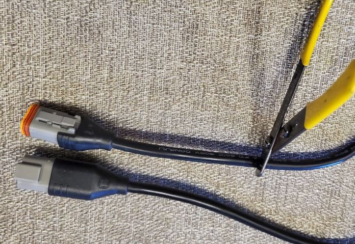
Take the 1 Meter DT Extension cable that you purchased and cut the off the flat end with the exposed orange silicone as shown in the picture below, approximately 1 inch from the connector end ( if using the short cable from eBay, cut right where the wires enter the unneeded connector). The short end with the Orange silicone connector will not be used electrically, but if desired can be used as a “dust cap” for the DEF head sensor connector when the DSS is not in use.
After cutting the cable, trim back the outer jacket about 4 inches and expose the 4 inner conductors. Be careful to not nick the wires.
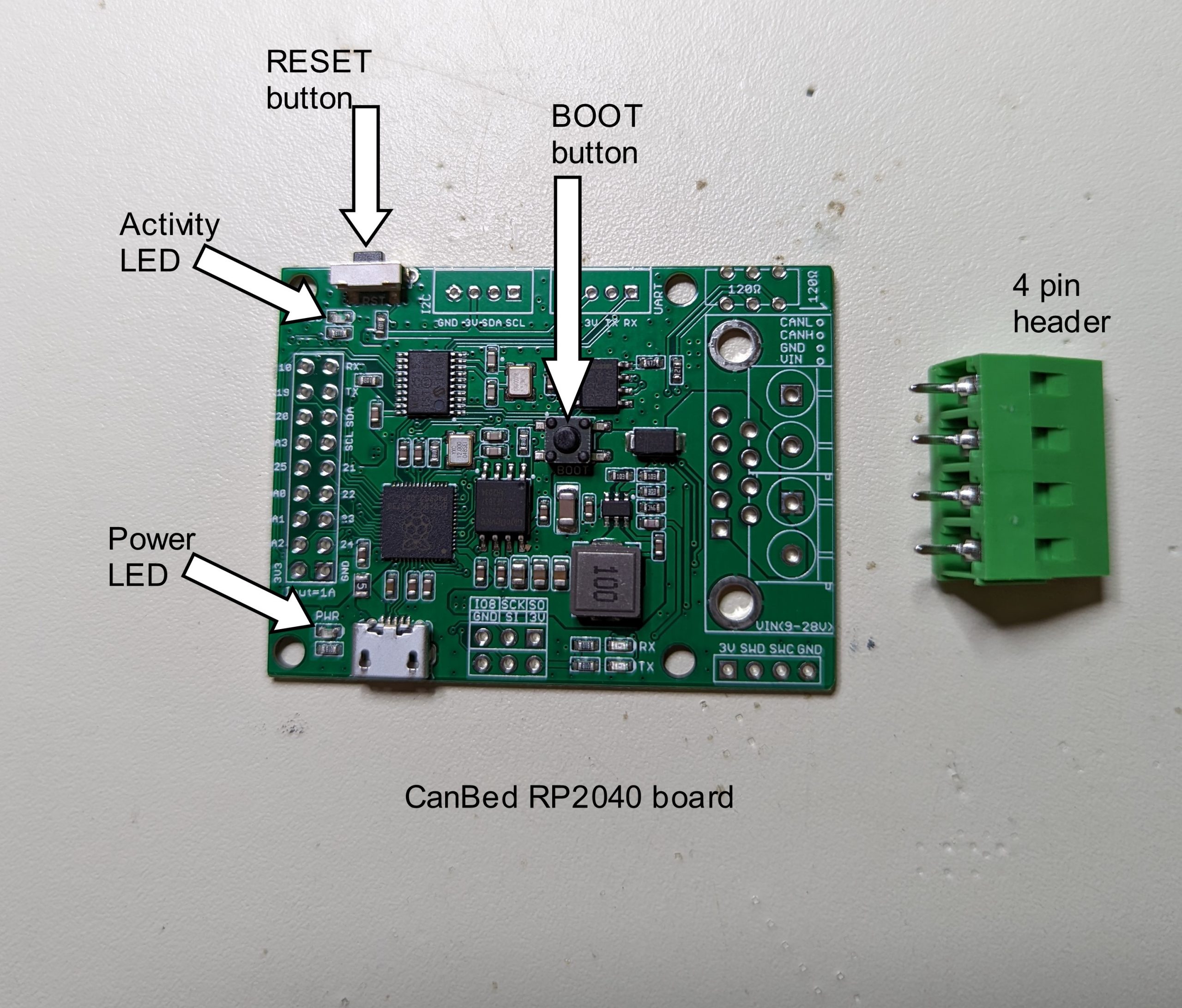
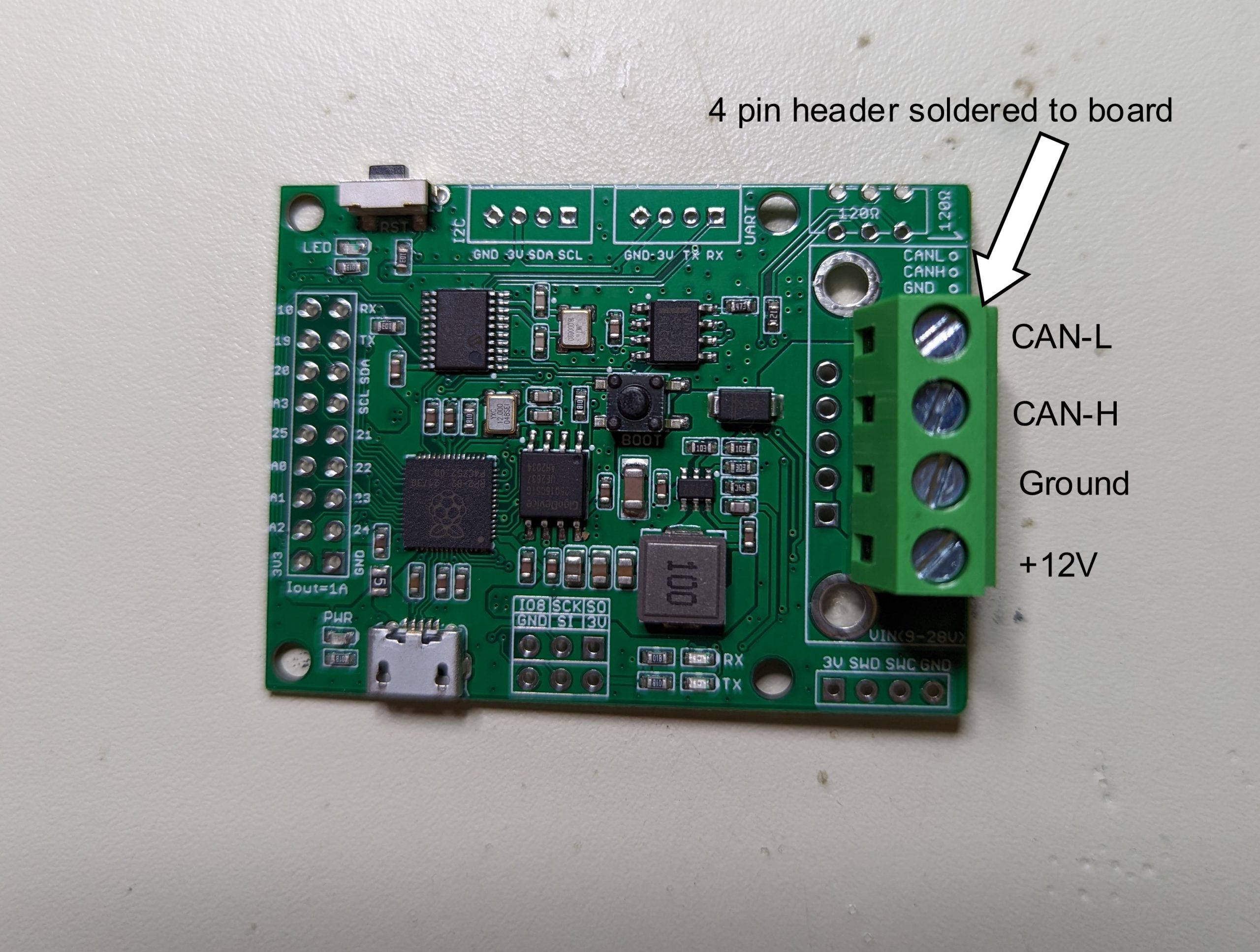
As mentioned at the beginning, the CanBed RP2040 needs to have a connector soldered to the board. The connector comes with the board. You can optionally directly solder the cable wires to the board if you wish. If you choose to solder the wires directly, you will need to feed the wires through the enclosure first, before soldering the wires to the board.
The connections on the 4 pin DT04 connector are: +12v, ground, CAN-H and CAN-L.
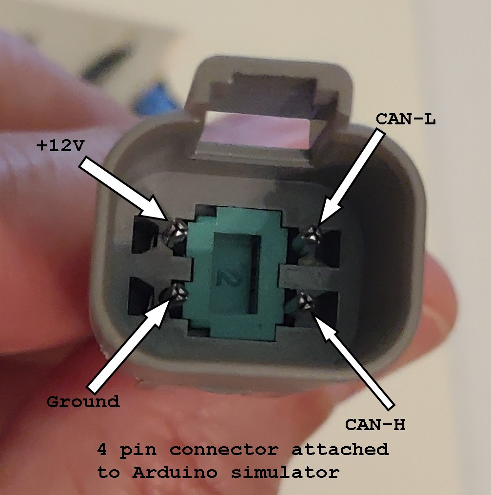
The wires associated with these pins (above picture) are connected to the CanBed RP2040 via the screw terminals. You will need to use an ohm meter (multi-meter) to determine which wire is connected to which pin, as the wire color codes are not standardized.
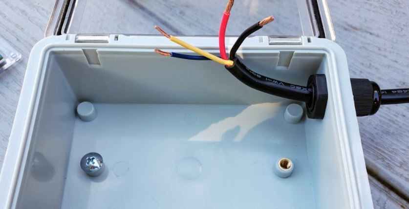
Drill a hole through the enclosure to accommodate the cable and gland nut (or grommet, whichever you are using).
Strip about 3/16 inch of insulation off each wire end and connect to the screw terminals. Make sure the slot is fully open as shown in the picture below. If the wires are too large, you can trim off a few of the strands.
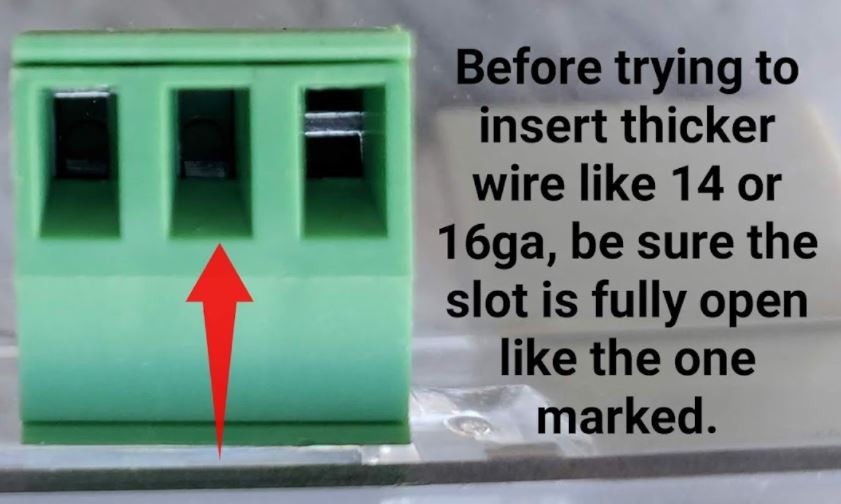
Insert the stripped wires into the slots shown in the picture below:
Tighten the screws to securely fasten the wires in the slots.
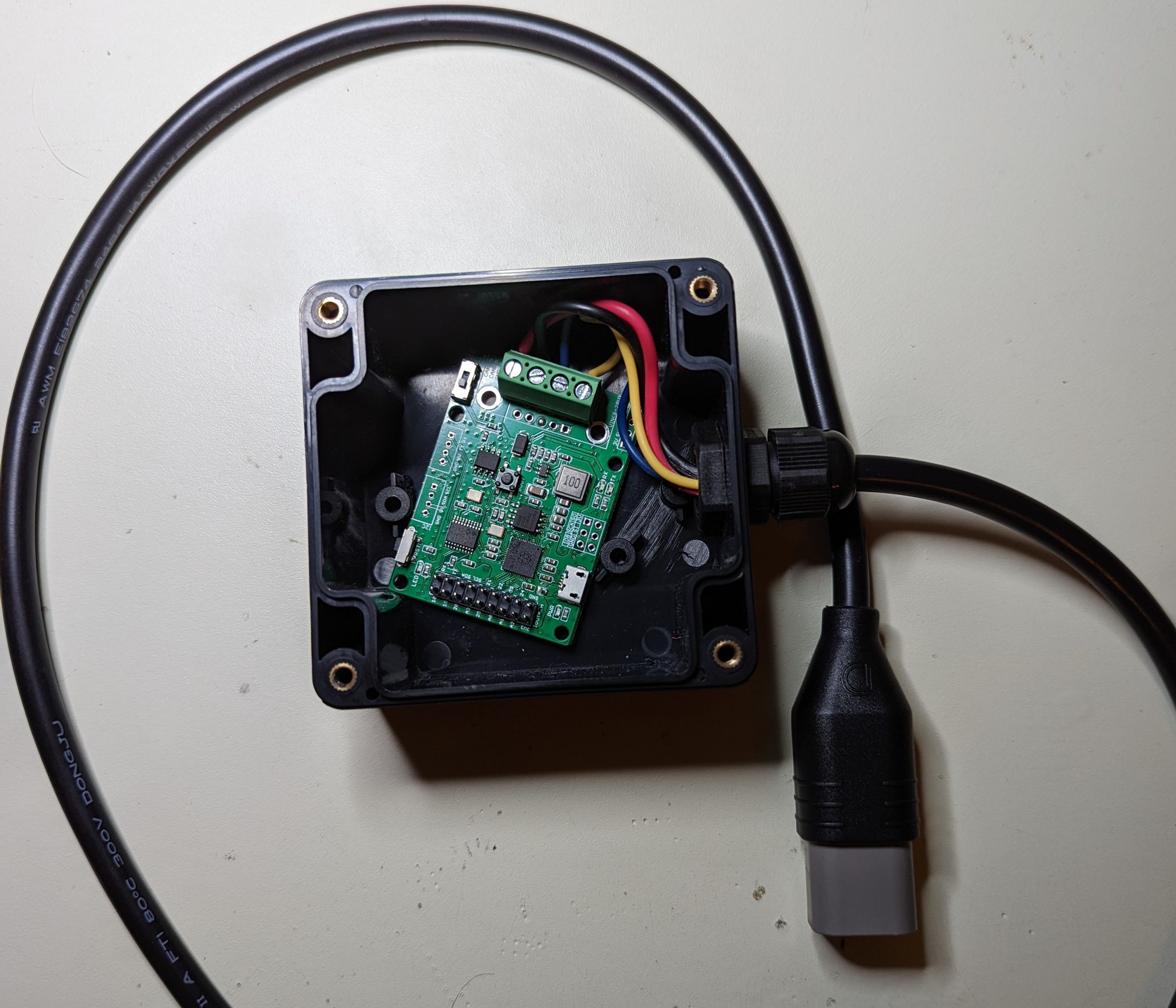
The finished board assembly can be secured in the box using Velcro. The smaller box will need one of the stand-offs in the bottom to be removed so the board will fit flat on the bottom OR the board can be mounted to the lid of the smaller box.
A completed assembly with larger box:

A completed assembly with smaller box:
NOTE: before mounting in the enclosure box, the CanBed RP2040 needs to be programmed! Please see instructions in the Programming section if this has not been completed.
Programming the CanBed RP2040 (Windows OS)
It is assumed that someone attempting to construct one will have a modest knowledge of a Windows based computer. The initial work was completed on a Windows 10 based machine, but it is expected that a Windows 7 or XP based machine will also work (USB drivers could be an issue). The computer will need to have at least 1 available USB 2/3 port.
The simulator software install file can be downloaded by clicking the download link below:
Download File
The file is usually downloaded to the “Download” directory on your Windows computer.
The download file (DEF_Sensor_Emulator_RP2040v1.ino.uf2) is a file that contains the compiled Arduino software appropriate for the CanBed RP2040 board. It is not necessary to install any additional software from Arduino or anywhere else.
1) Using a micro USB cable, connect the CanBed RP2040 board to your computer’s USB port. You should see a LED light up next to the micro USB port on the CanBed board. This indicates power to the board.
2) Open Windows File Explorer and find your download file (usually in the “Download” directory)
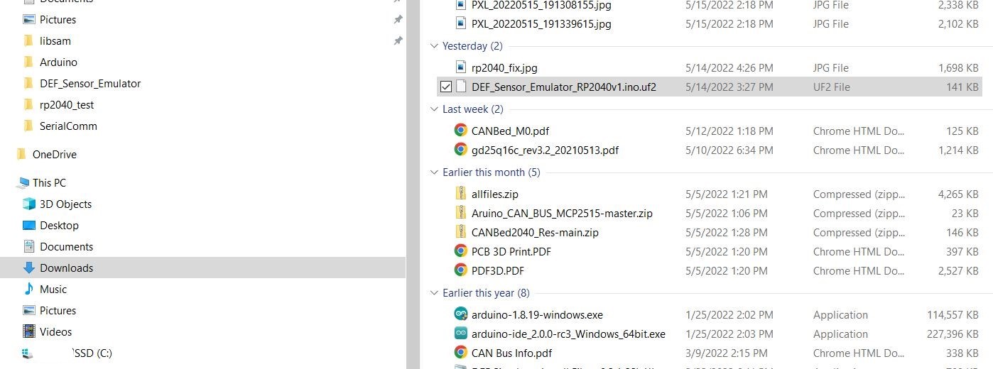
3) Right click on the download file name and choose “copy”.
4) Push and HOLD the reset button. While holding the reset button, push and HOLD the boot button. Release the reset button, wait about 3 seconds and then release the boot button.
5) A new Windows File Manger window should open. If one does not open, manually open File Manager and look for a new “drive” to be present and click on it.
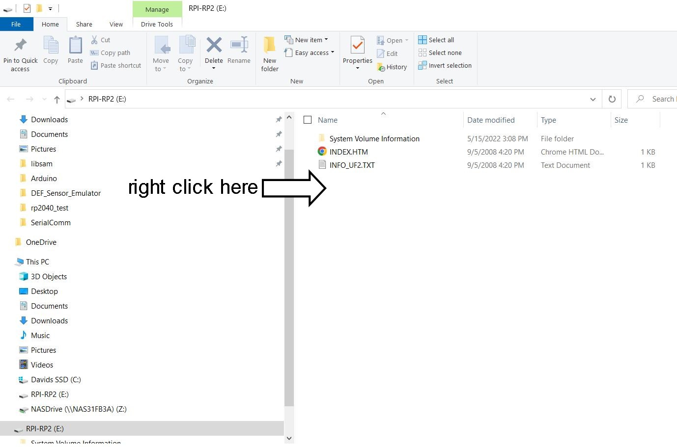
6) Right click in location as indicated in the above picture and choose “paste”. This will copy the download file to the RP2040 board. When the file is copied, the File Manger window should close.
7) Wait about 5 seconds and then the LED below the reset button should begin to flash 2 times quickly and then the flash repeats. This is a good indicator that the board is working as expected. There are 2 LEDs to the right of the micro USB connector, labeled RX and TX. These 2 LEDS will probably be on solid (usually red in color).
8) Unplug the board from the USB port.
9) Programming is now finished.
Video after programming:
Programming the CanBed RP2040 (MacOS)
It is assumed that someone attempting to construct a DSS will have familiarity with a MacOS computer. The computer will need to have at least 1 available USB 2/3 port.
The simulator software install file can be downloaded by clicking the download link: Download File
The file is usually downloaded to the “Download” directory on your MacOS computer.
The download file (DEF_Sensor_Emulator_RP2040v1.ino.uf2) is a file that contains the compiled DSS software for the CANBed RP2040 board. It is not necessary to install any additional software.
1) Using a micro USB cable, connect the CANBed RP2040 board to your computer’s USB port. You should see the PWR LED light up next to the micro USB port on the CANBed board. This indicates power to the board.
2) Open Finder and navigate to directory containing the downloaded file (should be the “Downloads” directory)
3) Push and HOLD the BOOT button on the CANBed RP2040. While holding the BOOT button, push and release the RST (reset) button. You will see the CANBed RP2040 show up as an external disk. Once it shows up (a few seconds) you can release the BOOT button.
4) Within Finder, drag the DEF_Sensor_Emulator_RP2040v1.ino.uf2 file to the RP2040 disk (mine shows up as RPI-RP2, yours may be different). Once the file has been copied, the CANBed RP2040 will reboot and will not longer be displayed in Finder as an available disk. You will likely get a warning that the disk wasn’t properly ejected. This is normal.
5) Once the CANBed RP2040 has rebooted, the “LED” light will continuously flash 2 times and then there will be a slight pause. This is a good indicator that the board is working as expected. There are 2 LEDs to the right of the micro USB connector, labeled RX and TX. These 2 LEDS will probably be on solid (usually red in color) indicating that the board is not yet connected to a CAN Bus (ie. your coach).
6) Unplug the board from the USB port.
7) Programming is now finished.
The below animated gif shows the process of installing the DSS firmware to the CANBed 2040 board.
Connecting to your motorhome CAN network:
- Make sure that before you unplug your def head that the ignition is turned off, then unplug your def head. You may need to cut a zip tie to provide working slack in the wiring.
- Plug the simulator into the connection to your chassis wiring where the def head was plugged in.
- Turn on your ignition, some or all of the fault codes should go away and the Check Engine and MIL (Malfunction Indicator Lamp) lights should extinguish within a few minutes.
- If some codes remain, to clear your codes you will need to turn your ignition on (let all systems come up, about 20 seconds), then start your engine and fast idle for 5-6 minutes, shut down for 90 seconds, turn ignition on (wait for systems to boot 20 sec) start engine and fast idle for 5 min. You will do this a total of 3 times on the 4 cycle the codes should clear to the inactive status.
Note: on older engines or engines with older ECM software, some codes may not completely clear on their own. In this case code clearing intervention may be required. This is something that is still under study, see the Troubleshooting section for more info.

Great instruction. Built 2 for powerglide. Absolutely PEACE OF MIND having these in the coach! Thank you gentlemen for making this happen.
I built the DEF Sensor Simulator – CanBed ATmega 32U4 and all appeared good. Plugged it into my 2022 power glide and got no faults. My coach has not had a failure so no codes to clear. Can I assume if simulator plugged in and engine running with no faults it’s a good build?
Very likely that the device is working.
Tested both units on a 2020 Tiffin Phaeton 40IH Powerglide Cummins 450hp. Both units tested outstanding. Exactly what your directions state. All codes cleared after turning engine off / on 3 times. Awesome job gentlemen. Thank you very much. Peace of mind.
Want to order from Longan Technology and they have the CANBed RP 2040 powered by the Rasberry Pi RP2040 chip with a high performance MCP2515 CAN controller and MCP2551 CAN receiver operating at CAN2.0 protocols in 133 MHz.
Is this the correct board?
Yes this is one of the boards that has been shown to work. Even though it looks nearly identical to the 32U4-based board, the programming procedures are completely different. Please double check and verify that you are using the correct instructions for your board and that you are downloading the correct (.UF2) installation file from GitHub.
Good luck
I have a longan rp2040 as well. I can’t get it to communicate or become available in the file manager. I tried different ports and different cables. Is there a primary program that must be programmed into the board first?
Check your email for a message
Archer, I just ordered the longan rp2040 as that is the only one in stock. Are there other instructions on using this board?
Thank you
Hi Rob. First, I presume you mean that you ordered the Longan RP2040 CANBED board that was linked to or was the same part number as the one listed on the DefSim web sight, right? I want to be careful because the RP2040 is just the particular model of microcontroller on the board but the board includes other components that allow the board to communicate on a CANBED network. Longan has other products using the RP2040 that are not designed for CANBUS uses, hence the caution.
Second I don’t know what you mean by “other instructions”. The instructions for using the RP2040 are different than the instructions for the several other types of Arduino-based boards that we have used but the instructions on the website specifically for the RP2040 are the correct ones to use.
If you have more questions let us know, we’re happy to try to help.
morning Archer, here is what I ordered
CANBed RP2040 is a CAN Bus development board powered by an Raspberry Pi RP2040 chip with a high-performance MCP2515 CAN controller and MCP2551 CAN receiver operating at CAN2.0 protocols in 133MHz.
From reading the previous post, it sounded like there might be different instructions or a different file to download.
You should be good to go. The instructions for using the RP2040 on this website are correct.
left off it was from Longan
Morning Archer,
Appreciate your replies, the board and cable went together easily and the software downloaded with no problems. Keeping my fingers crossed I won’t need it but hopefully will keep me from being stranded on the road if the def does have a problem. Thanks for putting this out for everyone.
I can’t get the RP2040 to show up either on my MacBook pro. Please send me an email with the solution. Thanks
Have you absolutely verified that your USB cable is a fully-functional cable and not just a “charging” cable? If you are not 100% certain then buy a new, known good cable. Have you double checked to make certain that you bought the correct single-channel RP2040 CanBed device? Did you order it by clicking on the link in the instructions? If not then you may have inadvertently bought the dual channel RP2040 board. Check to verify that the green connector that has to be soldered to the board has 4 pins and not 6. If there are 6 pins then you have the dual channel board and that board will not work.
With the scant info you posted that’s about all I can suggest. Try the stuff I mentioned above and if you still are having problems the repost with a little more detail please. Good luck
Im really interested in this build. Do you think there would be a way to make the emulator only work for a set amount of time after installation? Possibly with the installation of a real time clock?
Also, would it be advantages to add a battery? Im sure it takes a second to bolt and kick in. Could that be the reason that code keeps coming back? Im sure the emulator misses the first request due to the device booting up. If the emulator was working when the key is turned, the ecm wouldn’t have a chance to get that error code.
Now, we need to figure out how to get it sync Vins, so, it could be used on 2020 paccar engines.
Hi Reed. I’m not quite sure what I may have written that you are replying to but let me clarify some things.
First is that the DSS project was done to give some relief from an untenable situation where many people were being stranded for months due to an unfortunate confluence of issues. Specifically the widespread failures of a critical sensor intersected with a supply chain problem that prevented parts from being available for repairs. The situation is no longer critical. So the DSS project is not an ongoing project, no new code is being written and no additional feature development is being undertaken.
If you have the skills necessary to design, build and code a similar device you are welcome to do it. There is enough open source information available that you should be able to figure out what needs to be done. It’s not simple and its far from trivial but its clearly not impossible. So good luck but you are on your own.
Just out of curiosity what does “sync Vins” mean?
I am using a Windows 10 computer (I have also tried my MacBook) I get a USB device not recognized driver error when I try to bring up the Windows screen so I can copy the the file into it. It look like I need a driver for this device I have the CANbed RP2040-CAN Bus I
Do you see the RP2040 device in Windows File Explorer at all? Does it appear in Windows as a USB removable disk drive? Did you follow these instructions:
“ 4) Push and HOLD the reset button. While holding the reset button, push and HOLD the boot button. Release the reset button, wait about 3 seconds and then release the boot button.
5) A new Windows File Manger window should open. If one does not open, manually open File Manager and look for a new “drive” to be present and click on it.
”?
If that doesn’t help can you give any more info on exactly what you are seeing?
I am a higher end computer user. No window opens and there is no device in the folder. I get a driver error when I plug it in and when I go through the boot up process. I get the same error
When I go to device manager and look at the USB devices the port the device is connected to say it has a devices error and can’t correctly communicate with the device
I have tried to update the driver may different way and they all say I have the most recent driver
I need a driver specifically for this board or I have a bad board I hate to think the board is bad because I had it air shipped from China
I have tried multiple USB cords and only my data cords will try to connect to the computer and gives me this error
I have also tried my MacBook in this case my MacBook does nothing.
this is the exact error I get in device manager under USB Devices
Windows has stopped this device because it has reported problems (Code 43)
I did some trouble shooting recommendation I found on the web for this error and nothing worked.
Check your email & I will give you a call.
Hello,
I’m struggling trying to load the software onto the Arduino board. I get a no device found on COM 6 even though that is the verified port that shows. I do see the light blink sequence change as if it is downloading to the board and the windows pc makes a sound similar to when a jumpdrive is plugged in. Is there a method to verify the software was completed successfully? The board I have has a reset button but no boot button btw.
Thanks, Don
Don, check your email now. 740PM Central, Monday July 18
Thanks Vic for the quick reply and help. After using the software file for the 32U4 module it worked!
Don
I have a 2013 Entegra Anthem with a Cummins ISL 450
Which def simulator will work for my coach
Thanks
We have always made the assumption that the DSS was only for 2016 and newer coaches because the widespread failures were most commonly reported after the “DEF Quality Sensors” were mandated by EPA in 2016. However, even though your coach would not appear to be prone to the failures, if your coach uses one of the common connectors on the DEF Sensor the DSS may actually be able to be used to substitute for a failed OEM sensor.
So if you would be interested in conducting a simple experiment I would be willing to send you a working DSS if you would be willing to connect it to your 2013 coach to see whether it works. Even if it doesn’t work I don’t believe it would cause any serious problems.
did you get a def simulator?
did it work?
thinking of getting one. had a def problem once with my anthem. do not want a repeat.
Hello,
I just assembled the CANBed RP2040 per your instructions and tried to download the software. Did the copy and paste and the Windows Explorer window closed per your instructions. The led next to the USB connection remained on, but no other lights came on. I repeated the download just to make sure but got the same results. Any suggestions?
Hi Dave, I’m just posting here for the benefit of anyone who may be having a similar problem. As we discussed on the phone it appears that you understand the programming process and followed it exactly but your new RP2040 just did not respond (ie no flashing blue LED nor red xmit/Rx LEDs. I can only guess that you got a defective board out of the box. Please repost here if you get a replacement and whether it programmed properly, thanks
i have the same issue happening. it did it to 8 boards.
Hi Andrew, check your email for a message. Reply via email please.
I live in Monroe GA and on 6/9/22 i flew 2000 miles to Las
egas to pickup a 2021 Entegra motorhome, super C on a Freightline chasis.
When I picked it up the motorhome at at NIRVC in Vegas, it was topped off with diesel fuel and DEF. I left Vegas, drove 200 miles to Flagstaff and the DEF and engine warning lights came on. I had to leave the motorhome at Freightliner in Flagstaff and fly 1800 miles back home until they could check it out.
The problem was,before I took possession of the motorhome ar NIRVC, someone put diesel in the DEF tank and ruined the system. NIRVC will pay for repairs, but I have been waiting for parts for over 2 months with no indication when the parts will be delivered to Freightliner in Flagstaff.
Will the DEF Sensor Simulator work when the DEF system is totally inoperable? Any advice greatly appreciated.
Regards,
Roger
Wow! I’m sorry for your misfortune and I hope all works out in the end. You do pose an interesting question though. First, the fact that you drove a couple of hundred miles before any sight of a problem is weird. The DEF ‘quality’ sensor should act almost instantly in reporting that the specific gravity of the fluid in the tank was out of tolerance. The only thing that might make sense is if the tank had enough real DEF in it that was at the bottom of the tank and the Diesel fuel was floating on top. The quality sensor is located are the very bottom of the DEF sensor assembly as is the DEF pickup and it might just have took a while for the Diesel to get down to it as the DEF was used.
Your other question is more complicated. If the DSS was installed then it would send info indicating that the DEF was normal at 32.5% urea. So, it wouldn’t generate any faults itself. However I don’t know how the remaining sensors in the system like the NOx sensors, the reaction chamber temperature sensors, the ammonia ‘slip’ semsors etc would react to raw diesel actually being injected into the exhaust. But then again, some amount of unburned diesel has to be present anyway normally, right? And the amount of fluid being sprayed out of the DEF injector is also very small. So the bottom line is I don’t know exactly what might happen.
Thanks for your reply. Sounds like I would be taking a chance of creating additional problems; don’t need that. Just looking for some workaround to get it back to Monroe.
I just assembled the CANBed RP2040 per your instructions and tried to download the software. Did the copy and paste and the Windows Explorer window closed per your instructions. The software only took about 3 seconds to download and I never saw activity lights but the window did close. My “programmed” board looks just like your example, the Green LED next to the USB port is on, the Blue LED is flashing and the two Red LEDs on the bottom are lit and Steady. Does this sound normal, is there anyway to test other than plug into the coach sensor circuit? Thanks for all of the help.
That all sounds normal to me.
Good Morning,
I built the DEF Simulator and it worked perfectly, got me 3000 miles down the road and home. Thank you very much for the information and support. When I got home I unplugged my DEF Sim from the coach, and re-connected the defective head thinking I could get a mobile technician to replace my defective DEF head. That didn’t, and hasn’t happened. I disconnected the defective head, and re-connected my DEF Sim and started the coach. The original error codes returned and they are now “flashing” on and off on my dashboard. Any suggestions?
Hi Jeff. First, congratulations on being able to get home safely by using the DSS you built.
As to your question though, I suspect that if you follow the procedure to force the ECM to clear stored codes by starting the engine and allowing it to run for 5 minutes and then repeat 3X total, the stored codes should clear.
You indicate that I need “an ohm meter (multi-meter) to determine which wire is connected to which pin.” Can you explain further how that is done? Thanks.
Sure. This step is just a final check that your wiring is correct. The issue is that there can be various kinds of connectors that can be used, for instance you may use a pre-assembled cable/connector from Diode Dynamics or you might assemble one yourself from parts. The issue is you cannot rely on the wire colors to be consistent so using an ohmmeter (also know as a multimeter or a continuity checker) to verify that each pin on your connector is, in fact, connected to the correct destination on your board.
So for example if you are looking at the connector pins as show in the picture the pin on the upper left labeled +12V should show continuity to the screw terminal in the other picture that is also labeled +12V. Same for the pin on the upper right labeled CAN L, etc. you should also check that you Don not have a short-circuit from any wire to the other three wires.
If you used a Diode Dynamics cable/connector assembly but don’t have an ohmmeter you are probably safe just verifying that the wire colors at the board end match the ones in the pictures here.
Thanks!
Any chance of this working on heavy equipment? Running j1939 and has the same 4 pin DT harness connections for def header.
You won’t know for sure until you try it, but yeah. I would say that there’s a 99.9% chance that it will work, especially if the unit has a CM2350 ECM. Let us know if you try it & whether it worked.
We connected one to an industrial cummins engine on a potato separator and it works great. It just might (yes it has the J1939 connector as well)
Thank you all for this needed tool (assembly). I am building two of them. One for myself and one that I can send out to stranded individuals. Freightliner Chassis with Cummins ISB6.7 engine (2013).
Used the CanBed RP2040 from Digitec and have successfully programmed both cards.
Question is, where do I splice in or install connectors if I can not find the correct connector? What I find is a flat connector near the DEF header that has 5 wires in it and a smaller 2 wire connector. However, the header unit only has 4 flat spades where the 5 wire connector connects to it.
Am I to use a meter to figure out if the flat connector has the 12+, Neg, Can-L and Can-H? If so, what typ of signals would I be looking for on the Can-L & -H pins? Would the power need to be on and/or engine running?
I am afraid that I’m going to not make you happy. The DSS is only for engines made in 2016 and later that mark when the EPA began requiring a DEF “Quality” sensor to measure the specific gravity of the fluid along with the Temp and the Level. This info is on this page in the website https://defsim.myervin.com/cummins-engine-compatibility.
The problem is not just that your coach uses a different connector but it is that your coach used an analog sensor system so the DSS (being a digital device communicating on the J1939 Data Network) is fundamentally incompatible.
The good news though is the analog sensors are much less prone to failure so you will not likely ever have to deal with a DEF sensor problem. Also your plan to have a spare to offer to others in emergency need is truly admirable. If you want to use this forum to let others know that you have a couple of already-built units available to sell to cover your component costs please feel free.
Thank you Archer2 for your reply.
I have two units available for someone to purchase or use. If you are stranded and in need of the DSS, you can contact me with your shipping address and I will send one right out. When you are finished with it I ask that you return it for others to use or you can purchase it for $100.00.
Would like to buy one.
I have DSS (CanBed RP2040) units programmed and ready to overnight to anyone in need.
Please email me.
I would like to purchase one of the devices you have constructed.
Please confirm your unit will work on my RV: Freightliner XCS chassis, Cummins ISB 6.7L engine, 2017 Winnebago Forza.
I must admit I am completely confused by all the part numbers…
My contact info: jps0257@gmail.com
Thank you
I am interested in purchasing one of your units.
jps0257@gmail.com
I would be interested in purchasing a unit, I have all the parts to assemble my own but a bit confusing. My biggest concern is exactly where to plug the module in on my 2017 Cummins 600hp in a allegro Bus probably a 2016 engine.
Look at your DEF tank. On top of the tank you should see a circular assembly about 8 inches in diameter with 4 hoses and a 1/2 inch diameter corrugated wire loom. Follow that wiring about a foot and a half by touch until you find a connector that looks like the one in all the pictures in the instructions. You may need to unbolt some things to be able to get to it. If the connector looks like the 4-pin Deutsch then that is the connector that needs to be disconnected and the DSS plugged in. If the connector does not look like the one in the pictures then your coach is not compatible.
Does that answer your question?
Buying a prebuilt DSS from someone is not going to solve your problem of not knowing where to plug it in.
Do you still have above mentioned CanBed RP2040 ready to purchase. We have experienced DEF problem twice in our 2018 Valencia Renegade, Cummins engine, Freightliner. Sidelined & stuck for 5 days last time. Planning a trip in July & my wife is hesitate about going. Not sure we could make one. Please call or text if you have one, would love to purchase one. Thanks, Jeff Gavere. 407-435-1832
Do you still have a DSS unit that will work on my 2018 Newmar Dutchstar, Freightliner chassis, Cummins ISL 450 hp?
John Todd
jrtodd@msn.com
760-390-5227
Hi John, I don’t think Ricker Goldsborough has posted on this site in at least a year. I doubt that he will see your post. However if you dont have any luck you should just buy a RP2040 board from Digi-Key along with the correct Freightliner-style connector (and you should NOT follow the instructions for using the Spartan/Tiffin style connector) all the instructions as well as links directly to the parts are on this website. The total cost for parts should be less than $50 and the entire project shouldn’t take more than an hour start to finish.
Hi again John. I just checked and Digi-Key has the Freightliner-style connector in stock. Note that you also have to order at least 4 pins for the connector shell (they are listed on the same page as the connector body).
Here’s the link
https://www.digikey.com/en/products/detail/te-connectivity-amp-connectors/1-1703818-1/5428162?s=N4IgTCBcDaIIwFo4HYAMBmAHHTSQF0BfIA
Hello, just confirming that I ordered the board from Digikey, and the cable from Diode Dynamics the first week of August 2023, and the parts came Aug 7. Thanks for all the hard work and help setting this up!
Yeah, Digi-Key and Diode Dynamics have been great throughout this project. Honest, reliable folks.
Just let us know if you need any assistance with the build & programming, we’re happy to help.
I am also interested in purchasing a DSS unit. I have a 2018 37AP Tiffin Allegro Bus and had one DEF head failure two years ago and had to be towed to Rush Trucking in Reno and they installed a new DEF head in a very timely fashion. Please let me know if your unit will work with my Cummings 450 and a Powerglide chassis.
Mike, the website is meant to assist individuals who want to build a DSS for their own personal use. While the developers can’t and don’t police what users do with this info, they do strongly encourage folks to “do it yourself”.
The website and comment sections are for giving info and support to users who have questions about building their own device and we do not want it to become a platform for commercial users. I hope you can appreciate that.
So since you are literally on a site with everything you need to build a DSS why don’t you just use the info to order the parts and do it? It’ll be quicker, better and cheaper!
Also you may not have noticed but your comment is addressed to another user who has not been on this site for a long time so I’m sure they aren’t going to see your request.
Hi Archer-
After following and performing step 4. I can get the new window to open or can be found manually. I am not getting and errors on Window 7 Ultimate with service pack 1 64 bit operating system. Power LED lights up and the activity LED blinks 3 or 4 times before following step 4. Wounding what can be the issue.
Sorry typo error, I can not get new window to open. Using Longan canned Rp2040-can bus development board.
Thanks
I assembled a CANBED RP2040 version yesterday. On a Windows 10 PC, the first USB cable I tried was a charging only cable and the RP2040 did not appear in File Explorer when placed in BOOTSEL mode. After I switched to a different cable and placed it in BOOTSEL mode it didn’t open a new File Explorer Window but it did appear in the list of devices in the File Explorer Window that was already open. After copying the file, the RP2040 automatically reset, the blue LED started flashing and the CAN RX/TX LED’s turned on like the video shows.
I have 3 available for the powerglide units cm2350. 2016 and newer.
tested on 2020 Tiffin Phaeton 40IH 450hp .
email. beterlife@aol.com.
A note concerning the sale of pre-built DSS units. We are allowing a very limited number of offers to sell from people who have pre-assembled units for sale for the time being. There are a couple of caveats to be aware of however. The first caveat is that we would prefer the for sale listings be largely limited to sellers who built one or two units and then found that either the DSS were not compatible for their coach or they sold their coach or some other reason for finding themselves with a surplus unit. We may refuse to allow postings for what appear to be efforts to manufacture DSS units specifically as a for profit enterprise at any time and without prior notice.
The first reason is that the Development team designed these devices as an owner-built “do it yourself” project to help individuals get out of an otherwise untenable situation. A not insignificant amount of personal money as well as even more personal time and expertise was contributed by the team without any intent to make a profit. If you are building DSS units and using the software written by the developers to sell at a profit then you are essentially “misappropriating” (I use that term to avoid being insulting) their work.
The second thing is that we strongly prefer that each user procure the parts and assemble/program the devices themselves but in any case the most that anyone should pay for a pre-assembled device is approximately $75 USD plus reasonable shipping. Anyone charging more than that is operating well outside of the original developers’ intent and are, at the very minimum, showing a lack of respect for the people who made the DSS feasible in the first place.
Sir, I don’t sell these for profit. I’ve sent 3 out at 100.00 that included shipping to a couple of Tiffin owners . I understand your points and at no time do I do this for advantage. I offer these for piece of mind while traveling and APPRECIATE your hard work and would never jeopardize you or anyone who helped me out with this great information. If I can do anything for you and your team, I would be more than happy to help. Thank You very much. Bill
Bill, the post about commercial sales was not really directed at you. In fact your situation of having a couple of surplus units that you don’t want to go to waste is an example of exactly how it should be done and we have no problem with that sort of thing.
Your post just reminded me that I have been intending to post about people making a cottage industry out of building and selling at ridiculous prices. I should have made it more clear that I wasn’t talking about you.
I am having this trouble with a 2021 International RH with the A26 engine. Does anyone know what the def head plug is on this model?
I have assembled and programed the simulator. What is the esaiest/simplest way to test or confirm that it works?
Double-check all wiring to verify that it is correct and no has no shorts between wires. Disconnect your existing (good) DEF Head and substitute the DSS. Turn the key on, wait 2 minutes or so while watching for any alarms. Verify that the instrument panel DEF level goes to 75% regardless of the actual tank level.
If all is OK then start the engine normally and let it idle for 5 minutes while watching for any faults.
If all is normal then shut it down, reconnect the OEM sensor. Turn the key back in for a minute to verify no new alarms or faults.
Thanks for reply.
I finished building a simulator yesterday. Everything seemed to go as the instructions indicate. Since I currently do not have an issue I installed it and tested as you suggested to Ryan. While I never got any faults, my level did not raise to 75%. It stayed at about 1/3, which is what it was with the DEF head connected. I did look at the board and it had power with the blue led flashing slowly, the red led steady, and Tx and Rx were indicating transmissions. Although the Tx was brighter and seemingly more active than the Rx.
Do I have a functioning DSS?
Thanks
I built the Simulator using a Canbed RP2040 and everything went well, instructions were great. The only concern I have is in your pictures of the board in the instructions the completed unit shows a small switch on the corner of the board next to the wire connector but I can’t find anywhere in the instructions where it tells you to install it or what it is for. Am I missing something?
If you are seeing the small slide switch that would be on the upper right corner of the board assuming you are looking at the board with the 4-pin connector that you soldered in facing to the right, then that is an optional switch that allows you to switch an on-board 120 ohm termination resistor in and out of the CANBUS circuit. It is not needed for the DSS application.
Thanks, I appreciate the info.
Just built one of these and installed on a 2015 Hyster forklift with a 3.8l kubota diesel. Works perfect. Was getting a fault code for DEF quality, which I traced back to being the same code as caterpillar. Just thought you might want to know it works for this application.
Thanks for letting everyone know. What kind of connector did it use, the DT04 or the black & yellow Freightliner-style?
Just purchased a Seeed Studio CANBed Dual – RP2040 Chip-Based Arduino CAN Bus Development Board with 2 Independent CAN Bus Interfaces(CAN2.0 & CAN FD), 133MHz CAN Controller for Car Data Reading.
Started the process to transfer a file to the CanBed RP2040 I don’t see the unit respond past step 6 paste the file “DEF_Sensor_Emulator_RP2040v1.inouf2”
I’m stuck getting past step 7 Wait about 5 seconds and then the LED below the reset button should begin to flash 2 times quickly and then the flash repeats. This is a good indicator that the board is working as expected. There are 2 LEDs to the right of the micro USB connector, labeled RX and TX. These 2 LEDS will probably be on solid (usually red in color).
Instead when the unit reboots the only light on the unit is a sold green, no flashes nor are the RX/TX leds illuminated.
If I reopen the folder in the RPI-RP2 there are only two files in there
1-index
2 INFO_UF2
the file we pasted “DEF_Sensor_Emulator_RP2040v1.inouf2” is not in the directory.
I’m at a loss for what steps to take.
Many thanks for your assistance.
I’m going to take a look. Watch for an email soon.
So Devoir, did you figure it out and get it to program? I sent you a couple of emails but didn’t hear anything back.
I just noticed that the board you bought is not one of the ones listed as suitable. Yours has 2 CANBUS ports which leads to it having a completely different CAN controller chip and that means the program may not operate correctly since it depends specifically on pushing data in and out of the CAN controller hardware. I don’t think that problem necessarily is related to your programming issue but it could be. The bigger problem is that it may not work at all. Can you go back to the well and order this one:
https://www.digikey.com/en/products/detail/seeed-technology-co-ltd/102991596/15976345?s=N4IgTCBcDaIIwFYCcB2AtHADGJTFIDYQBdAXyA
Vic,
I had wondered if that would be a problem with the 2CANBUS ports.
PS I didn’t get an email message stating anything was posted here.
I’ve reordered the controller
https://www.digikey.com/en/products/detail/seeed-technology-co-ltd/102991596/15976345?s=N4IgTCBcDaIIwFYCcB2AtHADGJTFIDYQBdAXyA
I ordered two of the correct units and they did correctly program per the instructions with the flashy lights… As soon as I can visit the coach in the correctional institute of Maintenance I’ll plug it in to watch for a response.
Quick question on timing. I built the DSS with the latest instructions. I tested the system and got no CEL on running the engine for 10 minutes. I have a Freightliner chassis and Newmar Dutch Star with Cummins 450 HP.
I do not have a current issue with my DEF head. This was done for an insurance for a planned long trip in 6 weeks.
Should I get a DEF fault at what time should I connect the DSS. I understand that we get a partial derate for a few 100 miles then followed by the 5 MPH derate. At which stage should I be connecting the DSS? Any suggestions?
Thank you again for putting all this effort to help your fellow RVers.
Best regards
Mahdi
Hi Mahdi, congrats on your apparently successful DSS build. In the event that you have a genuine DEF sensor failure (as confirmed by the three SPNs described in the “Understanding Fault Codes” section of the site) and that you aren’t experiencing some other, unrelated DEF code, my opinion is that you could reasonably wait until it is convenient for you to be in a safe and comfortable place for you the connect the DSS. I would certainly try to do it before the deration starts though. I don’t know how your specific vehicle is set up but on my Entegra I could easily install a DSS in the time it takes to refuel the coach.
Hello,
I’m looking for help with a DEF quality sensor bypass. For 24v systems. Is there any for sale?
Thanks for your help.
Hi Ryan, what sort of help are you looking for? If you use the Seeed Studio CanBed RP2040 board or the Seeed Studio CanBed AtMega 32U4 board they should both work with no modification on 24V DC vehicles. Just be careful when programming them because they do have very different programming instructions. They both feature on-board DC to DC voltage regulators that are specified for up to around 28V.
Archer2, thanks for the reply.
I guess more specifically, can a DEF quality sensor be emulated or simulated with the same hardware and software that you mentioned above ? I know the build listed on the page is for 12v Cummins specifically. But I’m looking at this build and thinking it could be applied to 24v cat emissions systems, as long as the can bus data will simulate appropriate DEF quality…
Hi Ryan, I’ll try to answer your question but it may be a bit complicated. Just to get the big question out of the way first, there is no way that I can say for certain that the DSS will or will not work on anything other that the Cummins CM2350 ECM that it was tested on. Here are the main variables that would have to be identified for any other system.
1. First, as far as the microcontroller hardware, the Seeed CanBed 32u4 and the Seeed CanBed RP2040 will both work in a 24 Volt system. They have built-in voltage regulators good for up to about 28V. The original CopperHill Arduino DUE with extended voltage interface would also work. The two older boards that used a piggybacked Seeed CANBUS V2 shield are not suitable for 24V environments.
2. The systems (ECM and various sensors and control interfaces) operate using the CANBUS standard. The standard allows for data rates of either 250Kb or 500Kb, the Cummins emissions network happens to operate at 250Kb and that is what the DSS is programmed to operate at so if your application/ECM runs at 500Kb then the DSS is not going to work.
3. In addition to using the CANBUS standard which is a physical layer standard that defines the voltages, data rates, etc. the Heavy Duty truck systems also use the SAE J1939 standard which defines exactly what data is sent on the CANBUS and defines the protocols for how the messages are formatted, addressed, verified as well. It literally defines all data items that can be used and how the data is interpreted. This is where definitions for PGNs, SPNs and FMIs are found. So, for instance the section in the published SAE J1939 standard for SCR emissions systems has several dozen parameters (PGN/SPN) that can be used. But the standard does NOT require that any particular data item be used, just that if it is used it must be compliant with the standard.
So, the DSS is specifically programmed to send everything that the Cummins ECM expects to see from a functioning OEM sensor. It also uses the address that Cummins expects as well as responding appropriately to any requests for data that it may get or send to other devices.
And that right there is why we can’t know whether it will work with any other manufacturers’ system. Cat or Paccar may very well require additional data in addition to or instead of the data that Cummins requires. There is certainly a very good chance that all DEF sensors behave the same just because it would be to everybody’s benefit to agree on a standard set of outputs to simplify designing systems and sourcing components but we have no way to be sure.
Bottom line is you have to just try it to see if it works. If you have access to the manufacturer wiring diagrams then identifying how to wire the interface shouldn’t be hard. The only four wires are for CAN_High, CAN_Low, +V and -V(Ground). It will either work or it won’t, there is no in between.
Archer2
Thanks for the detailed reply. I will get some hardware coming and give this a shot! Thank you
Ryan,
Not sure I have the correct board this is what I ordered from Amazon
Can someone verify Thank You
https://www.amazon.com/dp/B01EWOE0UU?psc=1&ref=ppx_yo2ov_dt_b_product_details
That is one of the earliest versions of hardware for the project and is no longer recommended. Technically it will work but not by itself, you will need to add an additional piece of hardware called a Seeed Studios CANBUS V2 that plugs in on top of the board.
I would recommend that you instead buy one of the latest boards from DigiKey like the Seeed RP2040 CanBed unit for around $15. It is complete and you won’t need to buy the CANBUS shield. There is a link on this site in the “Build It” section here:
https://defsim.myervin.com/canbed-rp2040-def-sensor-simulator
Go to that link and follow the instructions there.
If you can return the other board to Amazon for a refund then do that but even if you can’t do that then buying the RP2040 will still be cheaper, better and easier than trying to continue with the UNO that you bought.
purchased a Speeed Studio Canbed dual RP2040 board
it has a 6 pin connector instead of 4 but the pins are labelled so no problem there
it has the green LEd and two red LEDS that come on when plugged into the PC is this proper?
does this device work with Windows 11 because i cant see the board in explorer
Thanks
Hi Louis, the Dual RP2040 hardware has not been tested so I have no idea whether it might work or not. My guess is that, since it uses a completely different CANBUS hardware than the RP2040 that we tested and wrote instructions for here on the website, that it probably will NOT work.
Just curious though, why did you buy an untested board instead of just ordering from the link in the instructions?
i am in canada and it was just easier to order from Amazon and pay in Canadian dollars.
it was listed on Amazon as a Dual Rp2040
Seeed Studio CANBed Dual – RP2040 Chip-Based Arduino CAN Bus Development Board with 2 Independent CAN Bus Interfaces(CAN2.0 & CAN FD), 133MHz CAN Controller for Car Data Reading.
thanks
Thanks, that makes total sense. The software was developed and written by people way smarter than me so I can’t say for certain that the Dual RP2040 won’t work but I suspect that it would require a different library to be linked and compiled. The Dual board uses a Microcontroller chip for the CANBUS interface while the standard RP2040 uses a couple of dedicated CANBUS chips. For starters I would assume that there has to be a command syntax to specify which CANBUS channel to use in the dual environment.
However, as long as you already have the board you could certainly try to see if it will work. The worst that can happen is you might get some fault codes that you might have to clear. If you decide to try it please post back here and let everybody know how it went.
Thanks
Thanks for the instructions.
its amazing if you use the proper board the Sync cable (not just a charge cable) and windows 10 it is about a 3 minute job.
Any reason why the simulator wouldn’t clear the SPN 3521 FMI 18 code. It did all the other codes just fine. My buddy is still broke down at Disney
Check your email for a detailed response.
thanks we’re testing your suggestion
well tiffin sent a new def head. after installing that he drove about 4 hrs before the code went away. so figuring the Simulator would have done the same but didn’t drive it to actually test it
Kudos to you all for figuring this out. Lots of work I’m sure. I have started to build my simulator, soldering the 4 pin connector to the board, then drilled the hole in the box. Next I was checking the length of cable I would need by locating the connector on the DEF head. I seem to have a different connector than is shown. the connector I have is circular, with a stub set of wires coming out of the cluster (in addition to the the wires that connect the head to the engine or wherever it connects). This stub set of wires has the connector shown, but it has what appears to be a rubber plug in the end. In other words, it is not connected anywhere. I have pics of both connectors. Any insight as to what I am up against here ? Do I just remove the rubber plug and plug the simulator into that stub cable set ? Thanks in advance for your help.
Sorry folks, I need to correct my previous post. The connector that attaches to the short stub cable with the “rubber plug” inserted is a 2 conductor cable, NOT using the Deutsch connector as shown in these instructions. So, it looks like the 4 conductor connector that is attached to the DEF head (that I need my DSS cable to have) is a circular connector. Before undertaking this I checked the Cummins compatibility for my ISL9 as indicated in the instructions, so I thought I was good to go, maybe I missed a step. I have a 2014 Entegra Anthem with the Cummins ISL9 on a Spartan chassis.
Hi Craig, can you email the pictures of whatever you have but also please tell me what type of vehicle (Make, model, year) as well as what type and year engine it has. Send the email to VChanko.defsim@gmail.com.
I’m going to shoot you an email right now so you can just reply to that with the additional info.
Thanks
Hello Archer2, I would like say thanks for all the hard work done in making a bad situation, a little easier. I’m faced with the same issue as Craig Vest and I have the same coach as him. 2014 Entegra Anthem. Yes my ECM is a CM2350.
I have the Canberra Arduino can bus Rp2040 board plugged in, have the green light constant on & the blue light flashing twice. I’m at step #2 for programing.when I try to open the default sensor emulator rp2040v1.ino (1).uf2 file,, I’m asked how to open file & look in the Microsoft store. click OK, I’m given 2 software choices, Makecode for Andafruit & Bekonix Designer. How do I proceed?
Go back and carefully re-read the instructions under “Programming the CanBed RP2040 (Windows OS) section. Once the “.UF2” file is downloaded, AND after you push the Reset & hold buttons on the board, you will COPY the “DEF_Sensor_Emulator_RP2040v1.ino.uf2” file and PASTE it to the RP2040 that should have appeared in your File Explorer drive listing. You DO NOT need to “Open” the installation file, just copy & paste it.
CAN YOU CALL ME PLEASE, 630-460-1214. FILE EXPLORER IS NOT COMMING UP
Can you call me please, 630-460-1214. File explorer is not coming up. I have is plugged in and my computer acknowledged the devise but the usb port is not showing in “this PC”
I think I got it. The two red LED’s are solid & blue is blinking twice.
I cannot get canbed rp2040 to be recognized in my drives at all.
Good afternoon,
first of all I want to thank you for all the work you have put into this project. We have a 22 Cornerstone and I want to build this just in case. The digi board
you have a line drawn thru is back in stock now,is this the correct one to use ?
Thanks Bret
Digi-Key Electronics is showing 140+ units in stock. Just disregard the strike-thru and click the link
Thank you !
I received my board today and attempting to program with no success. On a Windows 11 laptop and following the instructions when I first plug in I get a solid green light and flashing blue. Press and hold the reset, press and hold the boot button, release the reset while holding boot for 3 seconds. Blue flashing light goes out, solid green stays on, but no window pops ND I never see it in file explorer. Any suggestions? I’ve tried several different cables that I know are good.
I sent you an email.
Attempting to program without any success. Cambed rp2040. I have used the recommended new cable for installation. I do not get a flashing blue light. I have tried multiple computers and cables with no luck.
I’ve had the parts for a few months, but literally just finished building the two that I bought parts for. While it’s not needed… yet… just a note to say THANK YOU!!! Our ’22 Tiffin reportedly has the “newer” style DEF head that uses a black tank (instead of the see through tank), but I still have better peace of mind knowing that I have these. THANK YOU AGAIN!!!
Will this work on the ECU CM2450?
Yes it will
Thank you
Thanks in advance will this work I’m Cummins ILS9 with Ecm 2250?
2013 Entegra Anthem
Hi Bill. Your 2014 was built before the EPA required the DEF quality measurement so your sensor is likely not a digital device and therefor it doesn’t use the CANBUS to communicate with the ECM. So the short answer is 1. No, the DSS is not appropriate for your vehicle, but, 2. The pre-2016 DEF sensors were not prone to the same problems that the 2016 and later sensors did so yours is not likely to experience a failure and de-rate. Plus the DSS is not compatible with a CM2250 ECM as far as we know.
Thanks so much for the info.
Bill
assembled the CANBed RP2040 per your instructions and tried to download the software. Did the copy and paste and the Windows Explorer window closed per your instructions. The led next to the USB connection remained on, but no other lights came on. I repeated the download on multiple computers just to make sure but got the same results.
Hi Jason. There are a few possibilities that could cause what you are seeing when you try to program your DSS. First is that the USB cable you’re using is a “Power only” cable, designed to charge batteries in a USB device and is not designed to support data transfer. Unless you are sure that your cable is a fully-functional USB then try a new cable. This is the problem 90+ percent of the time.
The second possibility is that you bought a DUAL RP2040 board instead of the single-channel specified in the instructions. The two boards look almost exactly alike. Look at the place where you soldered the green 4-wire connector to the board. If the board has 6 holes rather than 4, then you have a dual-channel board. The dual channel version uses a different hardware design for the CANBUS controller and it will not work with the current programming software.
The final possibility is that you just got a defective board from the distributor.
Please let me know if you are able to figure it out. If you still need help just repost here and I’ll get in touch with you to see if we can get it going.
Can this be set up to condition the def quality values and not level? we have a need for this but would like the level signal retained.
Sorry but there isn’t any simple way to accomplish that. The DSS was designed to be used as a temporary tool in the event of a total failure of the OEM sensor. In the scenarario for which it is intended there is no data at all (including level) being produced by the OEM sensor. What kind of vehicle do you have?
I have I have a 500HP Cummins 2016 Newmar. I have a five wire round plug coming off DEF tank. What would I need to build the simulator?
The DSS is not compatible with your DEF sensor wiring. Your coach was built prior to the EPA DEF quality reporting requirements and is an all analog or partly analog design and is not compatible with the DSS all-digital design. It is not a matter of just having a different connector, it is fundamentally a different technology. The good news is that sensors like yours do not suffer from the excessive failures like the ones built later.
I have a 2013 Tiffin Allegro Bus with Powerglide chassis and Cummins ISL09 with ECM 2350.
Will DSS work with this equipment?
No. Your coach was built before 2016 and before the problem-causing sensor type was used.
I guess I have the 2013 problem-causing sensor type. The symptoms/engine alerts are identical.
Thank you for the prompt reply.
Are you saying you are getting SPN 1761 FMI9; SPN 3033 FMI9 AND SPN 3364 FMI9 errors or do you mean you are getting Check Engine Light, Malfunction Indicator Light, etc?
I suppose it’s possible that Tiffin could have installed the 2016 and later EPA system and installed a new calibration into the pre-2016 ECM.
Does the connector in your sensor match the one in the DSS build instructions (ie 4-pin Deutsch type)?
Yes to 1761, no to the temperature and quality alerts. Check engine, MLIs, and numerous other DEF tank quantity related codes (1673, 3498, 3547, 3497, 3712 (red “stop engine”,) and 3714 (torque derate)
I just checked the sensor plug type and unfortunately there are two connectors for the DEF sensor—one with three wires, the other with two, and they are both rectangular. I suspect this is the proprietary “analog” connection for installations prior to 2016.
My plan is to replace the DEF sensor since I’m not aware of any other alternatives.
Thank you for your help and advice. I was really hoping the bypass would apply to my rig.
The build and software install were super easy. However in Tiffin 2019 40IH a few fault codes won’t clear including after the engine on/off sequence – the remaining codes are 4340, 4342, 4344. There were several others associated with the DEF sensor that cleared pretty quickly, which was great! Any advice is much appreciated.
Hi Steve, the 3 other codes you see (4340, 4342 and 4344) are all codes indicating problems with the DEF line heaters. These have nothing to do strictly speaking with the DEF sensor itself and the DEF Sensor Simulator does NOT provide simulated data for those faults. The problem is likely to lie in the wiring harness or a fuse. At any rate, the DSS will not be of any help for these coded.
I got a simulator that looks like the CanBed RP2040 in the picture. The prior owner said it did not work. Is there any way to test it hooked up to a computer?
Hi Jerry, did the prior owner say exactly what the problem was (ie didn’t light. Up with power applied, didn’t program successfully, appeared OK but didn’t clear codes or caused new codes when connected to a vehicle?). Technically speaking, there is a way to test the device without needing to actually connect it to a live vehicle but it requires special hardware and software that I doubt you would have.
One thing to check is to look at the green connector that is or should be soldered to the end of the RP2040 board. If it has 6 positions instead of 4 then you have a dual channel board and it will not work correctly with the existing DSS software.
If it does in fact appear to be the correct single-channel board then all I can suggest is to carefully check and/or rebuild everything and reprogram it from scratch using the instructions on this site.
Thanks for the quick response.
After looking at it more carefully it looks like a CANBED AT MEGA; blue circuit board rather than green, etc.
It is in a box without a window so no lights visible. He did not build or program it. He just tried it and it did not clear codes. Then he got a simulator from somewhere else and it worked after he let the engine run awhile. He said he heard there is a software update but I have not found anything about that. If there is, let me know and I will loading it. If there is no update, will reloading software help determine if there is a fault?
Hi again, Jerry. This website can be confusing but I’ll try to simplify. You will find that there are instructions on building and programming several variants of DSS. This is because since the first version was developed there have been several evolutions of hardware. So, they are:
1.The Arduino DUE board from CopperHill Tech.
2. Then the Arduino UNO & AT Mega w/CANBED HAT
3. Followed by the Seeed 32U4 CANBED
4. Finally the Seeed RP2040
Each of these have their own quirks/pros & cons including specific versions of software as well as different procedures in building and programming. The UNO/AT MEGA variants were developed only because the DUE from CopperHill was very expensive and hard to get but other than being cheaper and easier to find they were not a great alternative.
As of now (June, 2023) the only two hardware variants recommended are the Seeed CANBED boards (numbers 3 and 4 from above) with the RP2040 (#4 above) the favorite by a wide margin.
So all I know to tell you is that if it were me, I would salvage the container and the cable & connector from the one you acquired and just order the RP2040 board from the link in the instructions, program it and re-assemble using the salvaged components. The new RP2040 should be less than $20. The board you have is tedious to assemble and marginal from a technical point of view anyway.
If you just insist on trying to make what you have work (and I really advise against it since we have zero idea of how it was built and what it may have been subjected to) but all I can tell you is to go to the instructions for the UNO/AT MEGA boards on this website, try to rebuild it from scratch and try it on your vehicle to see if it works. Good luck!
Thanks for the information and advice.
I received my CANBed boards and solder the 4pin connector. Getting ready to upload the file, but noticed in the picture you provided that there was a on/off switch on the board next to the 4pin connector. Is that switch needed, I have one, but not soldered in place.
Hi Tom, that switch is not needed for the DSS application. There is no need to install the switch, just ignore it.
Hi !
does this work on european trucks too?
more specific MAN
I don’t know but I very seriously doubt it. Lots of potential differences from the physical connectors to the specific regulatory framework.
ok thanks for the response!
I received the RP 2040-CAN Bus board, P/N 102991596. Instructions look easy to follow but one question. The instructions only mention soldering the wiring 4 pin header board and the initial pictures do not show anything attached on the left side of the board. In the final pictures there appears to be a large multiple pin board attached. Does that need to be installed? Soldered?
Hi Jerry check your email. I’d like your phone number to speak with you and see what you are seeing/talking anout,
Thanks
How can you tell if your USB cord is a data cord and not just a charging cord? Ive tried a couple of different cords and I never get the device to show up so that I can copy the file to it. I’m guessing my cables aren’t the right ones to handle the data transfer.
The only ways I know of is either use the USB cord to connect a device that requires data transfer (like a phone, camera, MP3 player, etc) to see if the computer recognizes it and allows you to move data to and from the device or just buy a new USB cable that explicitly says it supports data transfer.
Your RP2040 CANBED device should appear in your computer Windows File Manager as a new removable drive named “RPI-RP2 (X:) as soon as you connect it with a known-good USB cable
WOO HOO! I went and bought a micro data cord and everything worked just like I read. I will never again be stranded for 5 days waiting for a new DEF sensor!! My question is this…I already have a new sensor and all my codes are gone but can I still plug it in and check to see if it actually works? What would I be looking for if I can? Otherwise, it is going to find a place in a cabinet and lie in wait for the NEXT time that stupid sensor craps the bed!
Good job David, check your email for a message regarding your questions,
Thanks
Can you use the seeed studio Canbed Dual RP2040 off amazon it has more connections but will it still work if you just use what you need
Can you use the CANBed Dual RP2040 and just use the hookups that you need
Just received three CanBed PR240 boards from DigiKey and was surprised to see a bag of additional components supplied with each unit. I was expecting only the 4 pin header. I assume that these ‘extra parts” aren’t necessary to this build and that only the 4 pin header needs to be soldered to the board, is that correct? At least that’s what seems to appear in the final assembly pictures; with the exception of the pictures of the completed boards in the small and larger boxes showing the 18 pin gizmo in place along with the switch in the upper corner of the board next to the 4 pin header. I did read that the switch wasn’t necessary if installed, but can be used as an On/Off for the DSS. Other than that I’m eager to get underway.
I believe Jerry Crawford had very similar questions, but I didn’t see an answer.
Hi Dick. Your assumption is correct. The 4-pin green header is the only component that needs to be soldered to the board as part of the assembly process. The switch is actually used to switch a 120 Ohm termination resistor ơn to the CANBUS, it is not an On/Off switch and as a matter of fact could cause unpredictable problems if it were to be used.
The 2×9 header shown in some of the pictures was used to add an LCD display to the board as an option. We never really pursued that project and there isn’t any documentation on this site concerning how to add it.
Also Dick, I replied too quick. I do not know what a “CANBED PR240 board” is. Is this a typo or are you going to try an undocumented board? If you are that’s up to you but please understand that we will probably not be able to offer any help if you run into a problem. The software is pretty much deprecated and frozen as-is.
Hello Archer, Oops, sorry ’bout that, total typo on my part. Yes, the boards are all the CANBed RP2040’s. Time for me to start paying attention…
Hi Archer, I just finished programming three boards and everything went beautifully, absolutely no problems – all lights indicating in sequence as required, it couldn’t have been an easier copy & past operation.
Also, thank you for the confirmation of the 4 pin header being the only item in the bag of parts to go on the board. Your terrific list of parts and suppliers; covered every component perfectly and eliminated a whole lot of sourcing. The total package of instructions with pictures is fantastic, you couldn’t have done it any better, absolute perfection.
Last of all, and most important, is another big thank you to say how much I appreciate the time and effort you have put into your DSS project; and then be willing to share the results with all of us. Having your creation on board our Dutch Star will definitely lower the anxiety level of having a future DEF sensor failure – not if, but when and where.
Thanks for your comment but the real heavy lifting was done by other people much smarter than me. I just respond to most of the comments because I have the time and I enjoy it. So congrats on your successful build and good luck.
Hi, I can’t open up the software download on my mac book pro.
I am trying to install it on CanBed RP2040.
Any help will be appreciated.
Thanks, Mike
Hi Mike. I am not a “Mac guy” by any means but I’ll take a shot. You should be able to follow the instructions here:
https://defsim.myervin.com/canbed-rp2040-def-sensor-simulator
But here is a synopsis.
You say you can’t “open” the file. You may be making this harder than necessary. With the RP2040 you do not need to open the file. You just copy the file from GitHub to somewhere easy to find on your Mac (ie the “Downloads” folder). Then you connect the board via USB to your Mac. Once connected, just push and hold the “Reset” button on the board. Then press and hold the “Boot” button. Next release the Reset button then release the Boot button. That should have caused the Mac to have a new “disk” appear & you just drag the install file onto the new drive.
That’s it.
Did you follow the instructions and still have a problem? Let us know & we’ll try to help.
I have a 2016 Bus with the ISL 9. Mine is the analog version with 2 connectors. One is a 3 pin, the other a 2 pin. My sensor is failing & I am stuck 1200 miles from home. The new part is on back order.
Do any of the DSS configurations address this version? Everything I’ve seen is for the single, 4 pin design.
Sorry Dave but the DSS devices only work for digital sensors. If I could help I would, good luck.
I have the small black box that’s shown above, but I’m not sure the best way to secure the board inside the box. Velcro was mentioned above, but there’s not a good place to secure the velcro to the inside of the box. Would like to hear others ideas.
Hi John, sorry for the delay. I meant to answer you earlier. Anyway, the main point is to somehow prevent the board from moving, mostly to avoid the wire connections from becoming loose. The board itself, as you know, has very little mass anyway. I’ve seen people use double sided foam tape, Velcro, adhesive dots, you name it. Recently I built one and for lack of anything else I just wadded up the plastic ziploc bag the cable came in from Diode Dynamics and put it on top of the board and screwed the lid down. No need to overthink this.
The RD2040 board I got has 6 terminal holes for the wires from the cable. It has can0 H and L, also can1 H and L. will it work as long as I make sure to use one or the other? Sorry if this has been addressed above but I could not find anything.
The RP2040 board I got has 6 terminal holes for the wires from the cable. It has can0 H and L, also can1 H and L. will it work as long as I make sure to use one or the other? Sorry if this has been addressed above but I could not find anything.
Thơm, as I said in the email unfortunately the dual CANBUS board uses a different chipset for the CANBUS transmission and the current software is not compatible with that board.
Sorry
Hi, thank you for the extremely detailed and well laid out solution for the DEF head problems. My codes are cleared on our 2021 Allegro Bus and it is back on the road.
Here’s my question, we will be travelling in freezing temperatures this winter does the failed head sensor control the temperature of the DEF?
Put another way, will the DEF in the tank freeze because the simulator says the temperature is above freezing?
That’s a tricky question. The DSS reports whatever the actual ambient temperature is so theoretically if it gets cold enough to trigger the ECM to send the signal to the engine coolant loop solenoid and start hot coolant circulating through the DEF heat exchanger coils then it will work normally. DEF freezes at 11°F and the entire system is designed to not be damaged if the fluid does freeze. However it will obviously not be getting injected into the catalyst chamber and I would expect the NOx sensors to begin to complain at some point if it were operated with frozen DEF.
Then if the ambient temp climbs to whatever the ECM set point for closing the heating valve then the solenoid should close and stop the hot coolant flow.
The iffy part is 1. The temperature being reported as the DEF temp is actually the air temperature so it may turn on the heating well before the 11° and more importantly it may keep the defrost cycle going for way longer than needed. And 2. We have no idea what the actual temps that the ECM uses to turn heating on and off are. My assumption is that the heater will be turned on well above 11° so that’s probably safe, but there could be a situation where the ambient air temp never climbs above the “stop heating” set point thus allowing the DEF temperature to potentially get to a fault-inducing level.
One fairly simple approach would be to install a simple ball valve in the engine coolant loop upstream of the DEF tank and you could manually shut it off or even modulate the flow to keep the DEF liquid but somewhere below about 80°. Actually, I suggest that such a valve (or some other way to block hot coolant flow) be installed anyway to handle the situation when the coolant solenoid fails and 200° coolant is flowing full tilt unintentionally through the DEF.
Since the DSS is intended only for short-term use in an emergency we calculated that this was an acceptable trade off.
Ok, thanks for the quick response. Good to know the DSS is using ambient air temperature.
In that case I may add a temperature switch in series with the 12v supply to the engine coolant loop supply solenoid. Epoxy it to the top outside of the tank, add some insulation over it and set it for about 20F…..
Hello, I like you build. I have meet your CM2350 requirements but not the DT-4, I have a J1939 9 pin -Y- cable. Can I just unplug the BAD DEF HEAD and hook right up to the J1939 9 pin to P,G, Can L, Can H and it work just fine till it is repaired?
James, I’m afraid that I don’t know exactly what you are asking. Let me take a shot though. I think you are asking whether you can just plug the DSS into the 9-pin diagnostics port under the dashboard. If that’s what you are referring to then the answer (to the best of my knowledge) is going to be “No”. That port appears to be managed by the ECM and it does not allow access to the “raw” J1939 emissions network data. It appears that the ECM “curates” the emissions data accessible at that physical port for use by a diagnostic tool. For instance if you have a total failure of the DEF sensor, meaning that the unit just stops transmitting anything, the ECM will still show at the 9-pin diagnostic port the sensor’s PGN’s but with all data fields set to 0xFF. This is clearly not what the raw data says (the raw data says nothing at all, the PGNs simply are not being generated and therefore don’t exist at all) but displaying it as a live PGN albeit with null data values makes total sense from a OBD troubleshooting perspective.
The DSS by its very nature must interface with the vehicle emissions network at the same point (or one electrically identical) as the OEM sensor.
If I have misunderstood your question can you resubmit it but with more details?
Especially the brand, model and year of manufacture of the vehicle you are working with
Vic
Hello, I inadvertently bought the RP2040 CanBed Dual board. It does not look like the compiled code will work on this board. Would you happen to have a version for this board? Or alternatively the source so I can change it to support this board. Understand if you do not want to release the source, I figured I’d ask.
Hi. You are correct that the compiled code will not work with the RP2040 Dual CANBUS board due to its using a significantly different hardware design. You are also correct that, for reasons we have made clear since the beginning, the project is only available as pre-compiled code. The source code is not and will never be made available to users.
So your only option is to obtain one of the recommended hardware solutions. Sorry.
Thanks for all the hard work putting the info together and helping out answering so many questions.
I am building a board to have as a failsafe for a Tiffin 2022 Allegro Bay built on the Freightliner S2RV chassis with the 6.7 ISB engine.
The board seems to have been programmed correctly ( reading the other posts, I have the red TX/RX lights)
Does anyone with an RV using the S2RV chassis know if this is the correct connector?
TIA
Hi Mike, I sent you a detailed email with suggestions and links rather than answering here.
Good luck with the Freightliner connector.
Good day Sir, I’ve built the simulator per your detailed instructions and loaded the program. The board lit up as described and as shown in the video. My question is there a way to test the board without plugging it into the rig? Or do I have to install, start the rig check the info through my BlueFire device, confirm operation, then remove, to assure it is correct? Thx
The most practical way to test it is to make sure the key is off then plug the sim in. Turn the key on and verify the DEF gauge goes to 75% and there are no faults after 5 minutes. If all looks good then power down and reconnect the OEM unit
Thx
2021 tiffin 340red 38LL on freightliner XCS chassis with Cummins 340. I can’t get to the def head connector to verify type without heavily manipulating the harness. Any info available if my connector is same as listed here for the freightliner XCM chassis?
Your best bet is going to be Tiffin and/or Freightliner Customer Support. They should be able to say for sure what connector is in your coach. Obviously I’m not looking at your particular coach’s setup but the connector for the OEM DEF sensors are usually less than 3 feet from the tank header to the sensor/vehicle harness connector.
However, one way or another you are going to have to figure out how to access your particular coach’s connector or the DSS unit is going to be of no use to you when you need to use it.
I dug it out and it looks same as the one in instructions for the freightliner xcm. I can see the yellow tabs. Thanks!!!
My Tiffin Allegro RED 340 provided constant voltage to the J1939 communications system. The ignition key does not remove power. I recommend removing power via chassis disconnect switch prior to connecting the DEF simulator.
If someone is using a DSS, will the ECM set a fault code because it does not see a drop in fluid level as the coach travels miles down the road? Thanks so much for all your work to make this simulator which helps us get to a safe location.
My project went smoothly using the suggested parts and the supplied programming.
No, it will not set a fault due to fluid level. The DSS is programmed to simulate DEF consumption
I followed all links to order recommended supplies and completed build instructions. When I attempt to program I can only get the device to show up in my mac by utilizing the boot and reset button. When I drag the download to the device I get a sound that the transfer was successful and the device ejects. I have a power light, a flashing blue light and 2 continuous red lights. Is there anyway to confirm the software has loaded properly. when I plug the unit in again on both a mac and pc it will not show up unless I press the boot and reset buttons again and I cannot find the software listed, so I reinstall again following your directions and get the same as stated above. Just looking for conformation that I am doing everything correctly.
It is normal that, even though the board appears as a removable drive, you will not see the programming file if you browse the fake drive.
I think I programmed the CANBED RP2040 board. I get the light next to the micro connector. I get the Blue light 2 flashes. However the rx and tx lights do not come on.
Thanks
Mike Sweder
You guys are the greatest. Built mine today for piece of mind. We camp in very rural areas with no cell service. This will allow me to continue to do this. I want to THANK ALL who were involved is developing the DSS.
You’re welcome
Does the 4 pin header come with the CANBED – ARDUINO CAN-BUS RP2040 board ordered from DigiKey? From reading above, I believe that it does, I just want to confirm.
Thank you!
If you are talking about the little green solder-in screw terminal interface then yes, it is provided with the RP2040 board
Hi –
I’m wondering about the slide switch mounted on the RP2040 (adjacent to the 4-pin header block). It looks like it came in the package with the board but is not mentioned in the instructions. However, it does appear in some of the photos. Is it necessary?
I apologize if I’ve miss this question in an earlier comment.
Thank you for all of your efforts in making this happen. I have not experienced the “failure” yet but, am sure I’ll feel better having this device with me if /when I do.
Ignore the switch. It’s not used in the DSS design
I am using MAC OS and when I click on the download I receive the following error msg. Unable to read the dictionary of the application or extension because it is not scriptable.
Any help would be appreciated.
Sounds like you are trying to execute the file. You can’t do that. You should just copy the .UF2 file to your local computer then drag it onto the DSS once it appears as a USB device.
I just wanted to thank you for creating this DEF Simulator. I was stranded with a Derate in 2019 in CO. Closest Freightliner was in Grand Junction about 100 miles away. Was towed in after waiting overnight in roadside rest for the tow. With this device I am now comfortable heading across the great west 100’s of miles from dealers. I also wanted to post that the device didn’t clear all codes but the BLUEFIRE did!
The device should clear all the codes but you must follow the procedure. Engine run for 5 minutes 3x in a row should clear all codes.
Hi Archer, I completed my DEF simulators, a primary and a spare, June 2023, all the assembly and programming went beautifully. I never did the installation verification test of checking the Dutch Star’s fuel gauge at 1/3 or 3/4 and assuring no codes present; but I will soon get at that.
I was reading through all of these questions and answers as a review and to see what was happening lately with the simulators. My question for you is whether or not I actually installed the correct board, even with what appeared to be all positive indications of a successful build and program installation. Somehow, I had missed one of your replies on June 4, 2023, regarding which board you were currently recommending when you replied:
“So, they are:
1.The Arduino DUE board from CopperHill Tech.
2. Then the Arduino UNO & AT Mega w/CANBED HAT
3. Followed by the Seeed 32U4 CANBED
4. Finally the Seeed RP2040”
“As of now (June 2023) the only two hardware variants recommended are the Seeed CANBED boards (numbers 3 and 4 from above) with the RP2040 (#4 above) the favorite by a wide margin.”
Here is what I installed from Digi-Key:
1597-102991596-ND
CANBED – ARDUINO CAN-BUS RP2040
Is there any difference between the ARDUINO and SEEED boards that would require me to change boards?