DSS connector plug for Freightliner chassis (XCM)
Credits: The following content was provided by NMBluept
Disclaimer: please use at your own risk, practice due diligence and verify that the information provided applies to and is compatible with your specific equipment and double check your work.
DSS connector plug for Freightliner chassis (XCM)
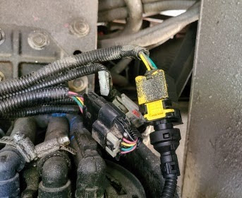
Note for DSS builders: the DT-4 connector used in the instructions for the DSS is not compatible with Freightliner chassis (at least with the XCM chassis). If your DEF Header connector looks like this picture, you will need to obtain/make a different plug.
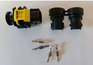
Parts list for the FL pig tail:
Note all parts except the cable are TE Connectivity part #’s
- Plug: 1-1703818-1
- Connector Cover: 965786-1
- Terminal pins (PCB Connector Contact, Male, Tin): 1-963745-1
- Cable: Copper Wire, Electric Conductor 4, Core 20 AWG
As with many of these type items it is difficult to purchase them in small quantities, most suppliers of these things sell in quantities of 100 or more. I did find that www.ttiinc.com has all the parts available in reasonable quantities:
- plug min qty = 3
- cover min qty = 8
- terminal pins min qty = 10.
- I found 5 M of 20 AWG 4-conductor cable on Amazon
[Editor Note: corrected plug part number.]
[Editor Note: Some or all of the above parts may be available from digikey in single item quantities.]
[Editior Note: to build this connector/cable assembly you will need to crimp the terminal pins to the wires in the cable. Most likely you will not have the appropriate crimp tool, however it can be done by soldering, or carefully with pliers. Having extra pins on hand is beneficial if you have never done this before.]
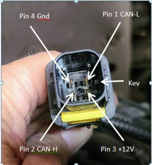
Pin assignments for the AMP plug:
Pin 1 = CAN-L
Pin 2 = CAN-H
Pin 3 = +12v
Pin 4 = ground
Editor Note: If you assemble the Freightliner-style connector according to the instructions there is no need to perform any of the steps under the “Verify the connections” section below as the connector wiring has been authenticated as correct by dozens of users since that section was written.
The section below is obsolete and is retained just for informational purposes.
Verify the connections:
Before connecting the cable to the DB9 [or other CAN board connector] verify the proper plug wiring by plugging the connector into the chassis wiring harness and measuring voltages with ignition key in ACC (except ground):
- Pin 1 CAN-l ~2.38v measure to ground
- Pin 2 CAN-H ~2.52v measure to ground
- Pin 3 +12V measure to ground >12v
- Pin 4 ground (verify with ohm meter, ignition off, to a solid metal ground = 0 ohms)
Note: this will create the codes associated with a DEF Header failure, but they can be cleared with a Scan Gauge or similar code scanning device.
Hints:
- 20 awg wire is easy to work with and easily fits the DB9 [or CAN board] screw terminals.
- To disconnect the connector pull out on the square yellow piece (gently pry it up if needed) until it “pops” out. The connector will then come apart easily.
- When inserting the terminal pins into the plug, if they won’t seat there is a locking mechanism that must be released by lifting up the yellow plastic part near the plug end. It will only move up ~1mm. Look into the wire end to see the yellow locks. Once the terminal pins are pushed in use needle nose pliers to pull them further and engage the locking tabs on the terminal pins.
- Double check your wire colors to pins in order get the wires in the proper locations on the DB9 screw terminals.
I got my connector, pins and seal plugs from Mouser Electronics and you can buy a minimum of 1 plug. I used part numbers 4-1703818-1 Plug, sames listed above only the plug is Blue, Terminal pins 1-963745-1 and Wire Seals 828904-1. I had been discussing this with Archer2 in another area.
Forgot to mention, I am dealing with a Freightliner Custom Chassis S2RV chassis.
Bill, you say that you got the connector part number 4-1703818-1 Plug? I hope I didn’t tell you to do that. It’s true that the insert is blue but that is not cosmetic. These connectors come in 4 varieties and colors and the first digit in the part number (1,2,3 or 4) is how they are differentiated. Each color/variety has a molded-in “key” in a different place so they will only mate with the receptacle part number that starts with the same number.
So, in short, the blue connector will not work. You need the black version part number
1-1703818-1 Plug. I am truly sorry if I gave you the wrong info.
No, it was all my fault and I posted about my mistake. The correct plug is also available from Mouser.
I want to correct my post about the Plug the plug I ordered does not quite fit, it has an index pin in the wrong location. I was able to trim the one pin and it fits but THE CORRECT PLUG IS 1-1703818-1
Sorry for the confusion. Everything else I ordered has worked and I will test tomorrow.
Just checking to see if we were successful. I to have the same chassis . The hardest thing for me is finding the connection on the DEF head. The space is very limited as you know. Is there anyway you could share a picture of the connection? If you can that would be great. Thanks
Go to this link. https://defsim.myervin.com/dss-connector-plug-for-freightliner-chassis-xcm Even though it says it’s for Freightliner XCM, it is also for other Freightlinermchassis. Scroll down and you should see several pictures along with the instructions for wiring. I’m sorry I don’t have any pictures that show where it is on your particular coach. All I can suggest is to track the cable from where it exits the OEM sensor until you come to the connector. The connector is usually less than 2 feet from the top of the OEM sensor and the connector is about 3 inches long, 1 1/2 inches square and is black with a bright yellow latch mechanism on the top. If the cables and hoses coming from the sensor are all zip-tied together you may have to cut the zip-tie(s) to be able to gain enough slack in the cables to see the connector. Good luck
I have assembled the connector for my XCM chassis, Just wanted to clarify for myself. When this is plugged into coach, I will need to be at some repair shop so fault codes can be cleared with scan gauge?
Also when I was assembling the box, I accidentally bumped reset on board, would this have rest board (program was already loaded)..It was not plugged into anything
Thanks
Hi Joe, congrats on your successful build. First thing, no you will not need to be at a shop. If you mean when you plug the DSS in in place of your OEM DEF sensor to test it, assuming you didn’t have any codes at the time and that you did the swap with the key OFF and that the DSS is wired and working correctly, you shouldn’t get any new codes. After you are satisfied that the DSS worked just turn the key off and swap back to the OEM sensor.
If you are asking whether you need to be at a shop if you have a failed OEM Sensor and you have the 3 fault codes (SPNs 1761, 3364 and 3031) and you plug the DSS in to avoid deration then also no. The vehicle diagnostics should see that there is no longer a problem and will clear the first 2 immediately then after 3 cycles of running the engine for at least 5 minutes each time the on board diagnostics will clear the 3rd (3031) and the amber Malfunction Indicator Light.
No shop required except to install a new DEF Sensor when available.
Archer, my question is when you verify the proper pin voltages it states that will trigger a DTC code that must be cleared at a shop or with some code erasing device. Correct? Im a little concerned about this causing an issue that I cant erase. Comments from those that have done this successfully appreciated. Thanks
Can you be specific about where you see that “when you verify the proper pin voltages it…will trigger a DTC code that…must be cleared at a shop…”?
I don’t think we say that anywhere. We do say that before you hook your device to a working vehicle that you test that there are no wiring errors (ie all connections are correct and no shorts or opens exist in the wiring). We also explain that if any faults are generated how to force the on-board diagnostic system to clear them upon reconnecting the good OEM sensor.
Quite a few folks have built, tested and even used the DSS without any problems.
Now that I reread your comment I see that you might have been lookin at some discussion of how to determine which pins on an otherwise unknown type of connector were +12, GND, can high and can low.
That doesn’t apply to the Deutsch connector or the Freightliner connector, both of which are already known and verified.
David, When I originally built the FL pig tail and was testing for voltages I created a condition which set the fault codes. Since I had a way to clear the codes I included that as a note in the procedure. If you follow the instructions provided by Archer2 there does not appear to be any need to be concerned with any codes needing to be cleared.
Also, I forgot to mention that pushing the “Reset” button will not erase the programming. It works just like killing the power to the board and then plugging it back in. It just stops and restarts the processor.
Thanks for response
We push off from Wis. to Texas tomorrow morning…Hopefully won’t need it
Joe
In the ‘hints’ section above it states “To disconnect the connector pull out on the square yellow piece (gently pry it up if needed) until it “pops” out. The connector will then come apart easily.” Is the referenced square yellow piece the female plug that in the photo shows overspray on the plug? Or is it referring to the yellow piece on “Plug: 1-1703818-1”? I tried to pull off the yellow piece from “Plug: 1-1703818-1” and all I did was break the weak prongs on the side (good thing TTI sold minimum of 5 🙂
Since I’m still waiting for parts, I have not tried to unplug the DEF sensor plug and so I am confused about it. I have received the “Plug: 1-1703818-1” and part of it has this yellow piece on it. I don’t really understand why that yellow piece is there, is it a locking mechanism for the female? I’d like to better understand this before I get my hands on the actual harness.
So…I re-read this section again for the umpteenth time and see that I overlooked the part about locking the pins into place. There is a place to pry up under the middle section of the yellow locking mechanism of the plug. That answers the 2nd part of the above question.
I’d still like to know more about disconnecting the female from this plug.
Jon, The square yellow part (covered with overspray in my pic) on the FL chassis connector will need to be pulled out about 1/2″ in order to remove the plug from the connector. The lock should pull out easily, I was able to pull it using my thumbnail.
Plug = end of cable from DEF Header
Connector = end of cable from chassis
I own a 2017 Tiffin Red 37PA on the Freightliner chassis and just built and tested the simulator using the CanBed board with the total build cost being around $75 using the information here. I encountered 2 problems programming the board using the directions, 1) none of my fully updated Windows 10 computers would recognize the board and returned a 43 error code, and 2) I had difficulty getting to the command prompt to input the programming commands. Researching the error in #, I found recommendations to try a different USB cable. It took trying 3 different micro USB cables that I had, but the 3rd cable finally worked as described and the CanBed board was recognized by my computer. On #2 the command prompt was not displayed as outlined in the instructions. But by entering the Windows key and the r key, the command prompt was listed and I was able to program the board as described. I then went out and tested the completed board by disconnecting the DEF tank from the connector and verifying the pins as suggested. I found that the specified pins in the instructions were correct for my coach. I then plugged in the simulator and then started the engine and verified that the DEF tank level was 75% so everything appeared to be working as designed. It did take a bit to figure out how to unplug the DEF head connector – the yellow piece on the coach wiring harness (not the DEF head male connector) had to be pulled out quite a bit and then they relatively easily pulled apart. My ScanGuage was not able to clear the codes that were set in testing the pin outs until I had run the engine for 3 five minute cycles. Hopefully, this information will help others who may encounter the same issues in their builds. Thanks for the efforts of those involved in making this solution available to everyone. I like carrying with me an inexpensive contingency for the potential failure of the DEF sensor.
Glad to hear you worked through the minor problems and successfully tested your DSS, congratulations!
As for the problems you ran into, you are not the first to find out that not all USB cables are fully functional. Some are actually only useful charging device batteries. They don’t have all the wires connected end to end. The “error 43” is just a typical, vague Windows message saying there is something wrong with a USB device.
Not being able to get to a command prompt normally is because of a Windows Group Policy that prohibits it. Was your PC ever part of a corporate environment or, alternately, is your Windows 10 installation one of the “S” variety? Windows 10-S comes with lots of security settings jacked up to extreme levels. I don’t know all of the things it impacts because the first thing I do with a Windows 10-S machine is to change it to standard Windows 10.
Thanks for the good feedback.
Archer2, my computers are a standard Dell desktop computer commercially purchased from Best Buy and a standard Microsoft Surface Pro 7 laptop also purchased from Best Buy. There is nothing special about either that I am aware of and I was not aware of Windows 10-S machines.
I don’t know what that was about then <> Glad you got it done.
What cable did you use?
I ordered the 20 AWG cable from the amazon link above. The cable arrived with white powder leaking from each end of the cable. Is this typical for others that ordered this cable?
I can’t speak for other people but it is common for cables like this (multiple insulated conductors inside a jacket or sheath) to have powder inside. It is similar to talcum powder and is used as a lubricant when the conductors are pulled through the outer covering.
Wanted to say THANK YOU to all the contributors!! I built two of these using the Arduino Due and both work on my 2019 Tiffin RED with Freightliner XCM chassis. The second unit will be going to a friend with a 2019 Tiffin Phaeton. Dash came up normally with no error codes when running so it looks like this will keep us from getting stuck or towed should we have the dreaded DEF failure.
Very much appreciate sharing this as open source. Sincere thank you to all.
Sounds like you have a knack for the electronic arena!
Not being a handy guy with electronics/wiring, I was wondering if you would be interested in selling an assembled unit for my 2019 Phaeton on the FL XCM Chassis?
I’m just about to start my build and I’m still confused about the statement in the last paragraph that says: “Note: this will create the codes associated with a DEF Header failure, but they can be cleared with a Scan Gauge or similar code scanning device.”
So to be clear: just testing the connections will cause the codes for a DEF Head failure, which means I need to buy a scan gauge as well so I can clear the codes after testing? I don’t want to get stranded just for testing my build.
Good point! That part was written before anyone else had used this style connector and nobody knew for sure that the connector wiring as shown was correct. It was to describe a way to determine for certain which wires on a specific vehicle carried which signals.
We have since heard from a number of users who have verified that the instructions are correct for vehicles built on the most common Freightliner chassis. You should be able to use the instructions and, after you double-check your work, just unplug your OEM sensor and plug in the DSS (all with the key OFF) and then turn the key on to observe the absence of any faults.
Even if there is a mistake and you get a fault, just re-connect the (good) OEM sensor and follow the “5 minute start and idle 3X” procedure and the onboard diagnostics will clear any codes-no scan tool necessary.
Thank you very much for clarifying. I will carefully put this together and hopefully all goes well. Very thankful for this site!
I have been able to order all of the pieces required for the FL chassis except the pins for the connector. Everyone seems to be out of them with long (2 mts or more) lead times. Can anyone help me out? Thanks in advance.
Hi Ernie, Digi-Key says they have plenty of the same part except in silver plate Part number is 1-963745-2. They are not cheap at $1.25 each!.
Here’s a link to the Digi-Key online catalog:
https://www.digikey.com/en/products/detail/te-connectivity-amp-connectors/1-963745-2/2331406
I ordered and received all the required parts (I thought), but today went out to find the connector on the coach DEF system. On my 2013 FL XCL chassis (2014 Winn Journey), I could not find a connector that matched the 4 pin purchased. The connector with a yellow pullout tab is 12pins. The only 4pin connectors in the system are flat (in-line).
Advice? Thanks, Dan
Hi Dan. I’m sorry to tell you that your DEF sensor is an analog device and is not compatible with the DSS. It’s not just that the connectors are different, but is that the way it operates is completely different from the 2016 and later Sensors. The good news for you is that your sensor is not vulnerable to the same epidemic of failures as the digital units are, so there’s that.
You might be able to sell your parts to somebody else by posting here and/or IRV2.COM.
Well, I guess that’s overall good news!
Thanks for the reply Archer2
I have a set of parts for freightliner chassis if anybody would like a good deal on them!
Dan,
I will purchase if they work for 21 Dutchstar on FCCC.
Email me at tomis8@gmail.com
Thanks.
Dan,
Do you still have the “freightliner chassis parts? What part numbers etc? did you build the Simulator or just have the parts to build it? I’d be interested as I’ve been building the simulators for folks but need 1 freightliner set. If not do you have an extra freightliner connector, pins etc?
Do you have any more freightliner dss to sell?
I’d be interested in buying a built simulator – do you have any available?
Does this mean my 2014 Allegro RED 33aa on a Freightliner XCM frame. 6.7 does not have the DEF sensor problems like the newer systems?
Correct
Archer2, It looks like the “note” in my original document is causing some unnecessary confusion. Can you remove it?
Thanks
Done! Thanks for your help.
I found that DigiKey and Mouser are out of stock for the plug with availability not until late August. However, arrow.com had everything.
Thanks to all who contributed! The simulator and this connector work on a 2018 Freightliner XCR chassis (Thor Aria, Cummins B6.7) as well as the XCM chassis. I already had an Arduino and can-bus shield v2, so the hardest part was sourcing the parts for the FL plug. I found the plug and pins at arrow and the backshell at digikey.
Question about connectors and model year. Will this simulator solution work on our 2016 XCM? I’m not seeing a connector that looks similar to the one you highlight in the Freightliner section of this page.
What does the connector in your ‘16 XCM look like? Does your vehicle have a DEF quality sensor as well as DEF Level and DEF Temperature sensors? Are you certain that you are looking at the right connector?
Thank you so very much for teach us so well to put this solution together. Your instructions have been invaluable and your pictures most helpful. Mine was for a Freightliner chassis. I tested it today and it seems to work without triggering any check engine lights. I do not have an issue with my DEF so far but planning a cross country trip so the added insurance is great to have.
All the best.
Mahdi
Hello,
I have a 2018 Newmar diesel motorhome on a Freightliner Chassis and my def sensor has gone bad as described on this website. I built the Arduino DUE original simulator with the correct plug as described and downloaded and installed the software. I also got on Cummins website and put my engine serial number in to
verify I had the correct ECM which I did. My question is when I plug in the simulator and turn on the key none of the lights on the dash go out and I am unable to start the motorhome. I will also add that the motorhome did derate when this happened and I had to have it towed to my house since it would no longer operate. Is there anything you could suggest that I might try to get the codes to clear? I also did check that the board does have power when the ignition is on.
Hi Steve, there are a few things that may be going on, but without a little more info I can’t say exactly what is happening so I’ll take a shot.
First thing is to verify that your coach has the exact 3 SPN/FMI fault messages that indicate a failed sensor. Those are SPN 1769, SPN 3031 and SPN 3364 and all of them should also show an associated FMI 9. Can you verify for sure that those are the codes you got? There are a number of faults that will also light up the CEL and other warnings (doser pump, NOx sensors, DPF issues, etc) but which are not related to the DEF sensor. So it’s not enough to have a fault (even an emissions fault) but it has to be the the correct fault for the DSS to have any effect.
The next thing is whether you in fact did successfully program the DUE board. Are you sure that you got the “Verify successful” message at the end of the firmware loader messages?
It is possible that you may have a wiring error. Either wires going to the wrong connector pin or two wires shorted together or a bad connection, etc.
Another possibility is that your DUE may just be defective. The quickest way to test it would be to just go ahead and order a new RP2040 CANBED board from DigiKey at this link:
https://www.digikey.com/en/products/detail/seeed-technology-co-ltd/102991596/15976345?s=N4IgTCBcDaIIwFYCcB2AtHADGJTFIDYQBdAXyA
This board is only $16. It will need to be programmed according to the instructions on this website. Note that it uses a different file that you’ll need to download and the programming procedure is different but just follow the instructions and you will be fine. You can reuse all of your other hardware like cable, connector, enclosure so you’ll only be out the minor cost of the new board.
I’m going to shoot you an email with all of this stuff so you can connect with us there instead of the comments section of this site.
Thank you to all who have came up with this! We were stranded in Vegas for a few days last month. I wanted to try this out but we were stuck and no way to get the parts in time. $2600 later freightliner had us back on the road. I sure wish I had this! Just finished my build, tested it and it works great! A great tool to keep on board! I had to make/crimp the Freightliner connection. It’s not too bad, it just takes some patience.
Thanks for all the help you folks have provided!
I have a 2022 Newmar New Aire with a frieghtliner chassis. I built my simulator using the frieghtliner instructions. The yellow plug one. I finally really looked at the DEF head and don’t see a yellow connector. I took pics but not sure how to attach to this note. Would love anyone’s thoughts. thanks!
I have a 2015 Winnebago Journey ISL9 with the proper ECM CM2350. From the image (https://www.skywaresystems.net/temp/FreightLinerDEFHeader.png) is the red arrow pointing to the proper plug and will the plug described in this section for Freightliner work?
Thanks for your help and maintaining this site!?
Generally speaking coaches with engines built before 2016 do not have the same high rate of failures that the 2016 and newer ones have. They have a different, analog, sensor and the DSS is incompatible and won’t work.
Thank you guys SO VERY MUCH for this walkthrough and great information about the DEF header problem. We just had one die on our Freightliner M2 mobile shred truck, and because of you guys we avoided a $800 tow bill, could take the truck to the dealer on our schedule, and got it replaced under warranty.
A big thanks to Bmiller as well for the Mouser Electronics tip, I was able to get everything from them besides the water resistant cases, which I got 2 of from Amazon.
I got 2x of everything from mouser(we have 3 trucks) for $50 shipped. $10 for 2x cases on Amazon. Wow!
The programming is so easy and I’m very grateful for this free work. you guys are awesome!
Have you seen other connectors on Freightliner chassis? This is a 2015 M2 chassis. Connector is 4 pin, but rectangular with the 4 pins straight across
Not compatible. DSS will not work