LCD Add-on for the Arduino DUE (Original Build)
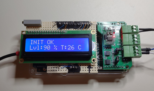
Adding a LCD module to your DEF Simulator is a fun extra project for the slightly more techie people. The current Simulator code already has support for the LCD module included. The module can display the initialization status, simulated tank level and simulated DEF temperature.
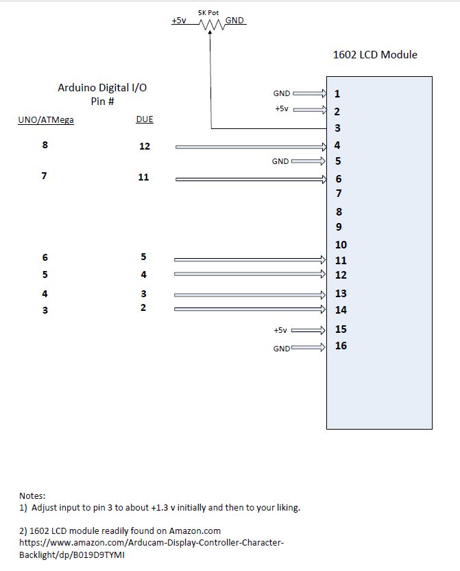
The LCD module uses different digital I/O pins on the Arduino DUE vs the UNO/ATMega2560.
The module can be built on simple perforated board or you can buy a bare “Shield” board from vendors on Amazon. As this is for the more “techie” people, I won’t get into how to solder or use a wire wrap tool.
Material needed:
Bare shield board: https://www.amazon.com/Electronics-Salon-Prototype-Arduino-Shield-CZH-LABS/dp/B01J1KM3RM/ref=sr_1_13?dchild=1&keywords=UNO+shield&qid=1631224556&sr=8-13
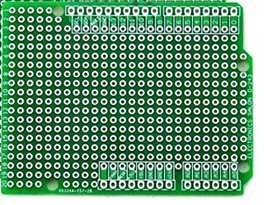
Even though this shield board is for a UNO, it can also be used on a DUE.
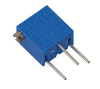
5K ohm variable resistor (pot): https://www.jameco.com/z/3262X-1-502LF-Bourns-1-4-Square-5k-8486-1-4W-12-Turn-Sealed-Trimming-Potentiometer_769080.html
Hook-up wire: https://www.jameco.com/z/901-2-Jameco-Valuepro-Wire-Wrap-Kynar-Red-100-Feet-30AWG-100-Foot-Rolls-_22631.html
Wire wrap tool: https://www.jameco.com/z/WWT-100-Jameco-Benchpro-30AWG-Wire-Wrap-Tool_2150361.html
Note: I used 30 AWG wire wrap wire, other small gauge wire can be used, but requires a soldering iron.
Schematic:
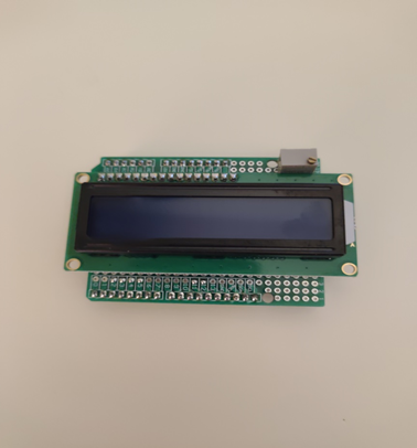
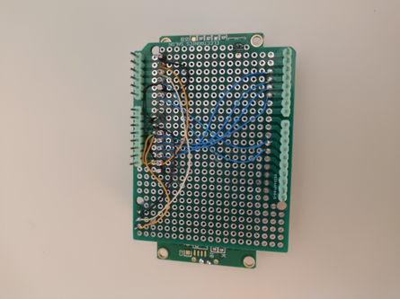
Pictures of completed assembly:
Can you add this to the Arduino UNO? and if so, do you have directions? thank you for all your hard work on this.
The pin-out for the UNI is slightly different. The schematic for the LCD shows the pins needed for both the DUE and the UNO/atmega.
Any possibility of adding a thermistor to communicate actual DEF temperature? Everything works great with UNO and CanBus shield, but frozen DEF will be a problem.
Has anyone tried this LCD add-on with the can-bed board?
First, thanks for the detailed instructions. I found an interesting comment regarding contrast pots that claims that you do not need to connect one side of the pot to 5V. It is post #28 in this thread:
https://forum.arduino.cc/t/replace-potentiometer-with-resistor-for-lcd-contrast/97022/27.
I wired my display up with just a 2K variable resistor between LCD pin 3 and ground and it’s working well.
A kind request for the LCD pin mapping for the CanBed with the ATmega32U4 processor. Having the LCD readout would provide a great deal of confidence that the simulator is functioning correctly.
Sorry, I forgot to mention it is a V1 board. Thanks.